@wesayso nice looking amp. Do I spy two power supplies?
Basically two mono-blocks in a single chassis...?
I also dislike most remasters lol.
I believe the (main) reason is due to the dynamic range compression commonly used.
With streaming radio or tv, they are moving away from that with the fairly new loudness standards (R128) . This will force most engineers to no longer destroy (squash) their mixes to be louder on the radio.
In fact since the db standard they sound much worse than uncompressed content.
RIP loudness war!!
I love your towers by the way.......
I just picked up 60 of the TC9's. Gonna try my hand at building some (corner) arrays similar to forum member "ra7".
Looking forward to see your build thread

I suppose I should/will do a build thread, but until then-
Summary-
Another attempt at trying to fit all those TC9's as tightly into a corner as possible, in a tall, triangular shaped enclosure lol!!
Edit- thanks for the nc535 build link, Ill check it out..
Summary-
Another attempt at trying to fit all those TC9's as tightly into a corner as possible, in a tall, triangular shaped enclosure lol!!
Edit- thanks for the nc535 build link, Ill check it out..
Last edited:
Anyone any experience with Hypex nc500mp-OEM amps?
I think I've got most of it covered, I just want to know how to connect the standby function with a flip switch to start up the amplifier? I may have more questions though (lol).
This is the data sheet: https://www.hypex.nl/documenten/download/918
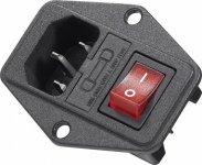
It may be as simple as connecting J6.3 (which is a standby voltage supply) to the J6.9 Input (PS Enable). Would that give me a proper startup/shutdown function behind a simple flip switch? I can switch the mains off too as that is a switched and fused standard 220 V input:

But I assume (allways a dangerous thing) I need to power up the SMPS anyway with a 'PS Enable' signal.
It's also confusing me to have 2 sets of speaker outs on the connectors (J5.1 to J5.4). To use this amp as a Mono subwoofer amp (which this is, right?) do I use both sets of speaker out combined or just the lines (J5.)3 and (J5.)4 as indicated.
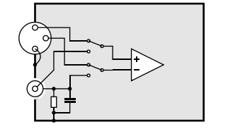
I also need to use RCA input and not the (obviously) preferred balanced input, for that I'd use the schematic from Bruno in this doc: https://www.hypex.nl/img/upload/doc/an_wp/AN_Legacy_pin_1_problems.pdf
More specifically the bottom example of paragraph 4.5 (though without the switch for balanced/RCA, just the RCA part of that schematic with a resistor and cap to earth, coming of the shield/negative outer part of the RCA input plug).
Sadly, I don't have a balanced out signal available that can feed the Sub amp(s), only RCA.
That's about it, working hard to try and finish up this year. I don't want to wait out another long winter, that time is much better spend listening and correcting my DSP.
Not sure if I can get all of it finished, but I'm willing to try! I have to mount the amplifier to the enclosure with all bells and whistles before I can get the Epoxy/paint out and finish up.
I think I've got most of it covered, I just want to know how to connect the standby function with a flip switch to start up the amplifier? I may have more questions though (lol).
This is the data sheet: https://www.hypex.nl/documenten/download/918
It may be as simple as connecting J6.3 (which is a standby voltage supply) to the J6.9 Input (PS Enable). Would that give me a proper startup/shutdown function behind a simple flip switch? I can switch the mains off too as that is a switched and fused standard 220 V input:
But I assume (allways a dangerous thing) I need to power up the SMPS anyway with a 'PS Enable' signal.
It's also confusing me to have 2 sets of speaker outs on the connectors (J5.1 to J5.4). To use this amp as a Mono subwoofer amp (which this is, right?) do I use both sets of speaker out combined or just the lines (J5.)3 and (J5.)4 as indicated.
I also need to use RCA input and not the (obviously) preferred balanced input, for that I'd use the schematic from Bruno in this doc: https://www.hypex.nl/img/upload/doc/an_wp/AN_Legacy_pin_1_problems.pdf
More specifically the bottom example of paragraph 4.5 (though without the switch for balanced/RCA, just the RCA part of that schematic with a resistor and cap to earth, coming of the shield/negative outer part of the RCA input plug).
Sadly, I don't have a balanced out signal available that can feed the Sub amp(s), only RCA.
That's about it, working hard to try and finish up this year. I don't want to wait out another long winter, that time is much better spend listening and correcting my DSP
.Not sure if I can get all of it finished, but I'm willing to try! I have to mount the amplifier to the enclosure with all bells and whistles before I can get the Epoxy/paint out and finish up.
Attachments

Thinking about the RCA input inside my enclosure, it's more like the first drawing in chapter 4.5:
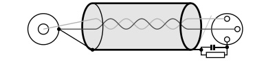
Where the left side is my RCA input connector, the right will be connected to the Hypex J4.2 (positive center), J4.1 (outer part of RCA) and the shield J4.3 (with the resistor/cap) as seen here top to bottom. (RCA input mounted insulated from the enclosure obviously, where the cable shield and outer ring of the RCA are connected together)
All aluminium parts of the enclosure (like the heatsink at the back of the sub enclosure) will be connected to mains ground. Do I get that right?
I've been over this before with koldby in the past, he'll probably laugh at my inexperience or lack of understanding.
I want to make sure I get it right, I'm a Mechanical Engineer by trade, not an Electrical one.
You know what you get when you mix steel parts with electricity, right! (lol)
Where the left side is my RCA input connector, the right will be connected to the Hypex J4.2 (positive center), J4.1 (outer part of RCA) and the shield J4.3 (with the resistor/cap) as seen here top to bottom. (RCA input mounted insulated from the enclosure obviously, where the cable shield and outer ring of the RCA are connected together)
All aluminium parts of the enclosure (like the heatsink at the back of the sub enclosure) will be connected to mains ground. Do I get that right?
I've been over this before with koldby in the past, he'll probably laugh at my inexperience or lack of understanding.
I want to make sure I get it right, I'm a Mechanical Engineer by trade, not an Electrical one
. You know what you get when you mix steel parts with electricity, right! (lol)
Attachments

Last edited:
just put a space heater in that garage and work there as long as it takes. Florida is still in the high 80's and I love my air conditioned garage
Going single ended (e.g. RCA) into the subs is always a worry. I had to buy an ART Clean Box for my situation - to make a AV receiver's sub output work with a pro amp. The ART Clean box is just an op amp doing the single ended to balanced conversion. You can build that into your amp....
that schematic you show keeps the RCA return isolated so it "should" work. its using the RCA return as if it were balanced without connecting the grounds of the two systems directly together.
Thinking about the RCA input inside my enclosure, it's more like the first drawing in chapter 4.5:
Where the left side is my RCA input connector, the right will be connected to the Hypex J4.2 (positive center), J4.1 (outer part of RCA) and the shield J4.3 (with the resistor/cap) as seen here top to bottom. (RCA input mounted insulated from the enclosure obviously, where the cable shield and outer ring of the RCA are connected together)
All aluminium parts of the enclosure (like the heatsink at the back of the sub enclosure) will be connected to mains ground. Do I get that right?
I've been over this before with koldby in the past, he'll probably laugh at my inexperience or lack of understanding.
I want to make sure I get it right, I'm a Mechanical Engineer by trade, not an Electrical one
You know what you get when you mix steel parts with electricity, right! (lol)
You also make a rca->xlr cable. In that way you can keep the balanced input on your amp.
An other point: did you look at the NC400 mono block kit? I have made a set and am very happy with the results.
This is how I would do it from reading the datasheet.
Wire your main power switch to the two prong connector J3, (switching this on will activate the standby supply) connect the Standby output J6.3 to the PS Enable Pin J6.9, this will then switch on and off the whole thing by using the main power switch.
From the data sheet
"5.1 Power Supply Enable
By asserting the PS Enable pin of the H-Bus connector the Main-SMPS is enabled. The Standby-SMPS is
enabled form the moment that the module is connected to mains. Therefore the Standby-SMPS can be used
to activate the Main-SMPS. When the Main-SMPS is powered up, the amplifiers will be enabled, providing
there is no failure and Amplifier Mute is not asserted."
Use J5.4 for Positive Output and J5.3 for negative. The reason for the two sets of terminals is because you can get an add on tweeter amp which will then use the other pins.
Use a balanced input connector to the amp on an XLR and wire it as a pseudo balanced cable by connecting the shield and cold (differential negative) together on the RCA ground pin as shown in the diagram. This still gives up to 40dB of common mode rejection on the input. Better than a straight RCA connection.
Last edited:
You also make a rca->xlr cable. In that way you can keep the balanced input on your amp.
An other point: did you look at the NC400 mono block kit? I have made a set and am very happy with the results.
I think I'll use an RCA input connector this time and wire it like that pseudo balanced cable. I can always open up the sub enclosure to change to balanced input at a later stage, I always keep my constructions serviceable for reasons like that.
A while ago I have thought about the NC400. However ever since I have the Goldmund clone it never entered my mind again
.I have the 250 W version, and it is correct what Fluid says about the standby switch. Just put a SPST switch between j6.3 and j6.9 and it works perfect.
As a sub amplifier only and as separate mono amplifiers in each sub-enclosure, I would not worry so much about the balanced to unbalanced connection. I have tried it with just connecting the - input to ground and in all of the Hypex modules (UcD180 UcD400 UcD700 and this ) never experienced any hum or noise.
Also just use J5.4 and J5.3 as outputs.
It is a fine sounding amplifier, and I think it will work great as sub amp. I plan to use mine as sub amp as well.
As a main amp, even if it is very good sounding, it cannot challenge your GM clone though.
This is how I would do it from reading the datasheet.
Wire your main power switch to the two prong connector J3, (switching this on will activate the standby supply) connect the Standby output J6.3 to the PS Enable Pin J6.9, this will then switch on and off the whole thing by using the main power switch.
From the data sheet
"5.1 Power Supply Enable
By asserting the PS Enable pin of the H-Bus connector the Main-SMPS is enabled. The Standby-SMPS is
enabled form the moment that the module is connected to mains. Therefore the Standby-SMPS can be used
to activate the Main-SMPS. When the Main-SMPS is powered up, the amplifiers will be enabled, providing
there is no failure and Amplifier Mute is not asserted."
Use J5.4 for Positive Output and J5.3 for negative. The reason for the two sets of terminals is because you can get an add on tweeter amp which will then use the other pins.
Use a balanced input connector to the amp on an XLR and wire it as a pseudo balanced cable by connecting the shield and cold (differential negative) together on the RCA ground pin as shown in the diagram. This still gives up to 40dB of common mode rejection on the input. Better than a straight RCA connection.
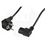
I have thought about skipping the extra on/off extra switch like that. But as I mount the complete assembly on the back of the enclosures I'd envision a seperate switch might be easier to get to to switch on/off. I've already ordered a 90 degree power cable to save space.
If I wire the RCA input like I mentioned to the Hypex amp, it would be exactly the same as putting the balanced input connector on the sub enclosure with an altered RCA cable like in the picture, right? I would hate to have to wait on more parts, I only want to be sure I have the right idea here. As said, if I ever change my mind it will be possible to switch things out.
I figure a balanced input would have 3 straight wires to the J4.1, J4.2 and J4.3 inputs anyway.
Attachments
I have the 250 W version, and it is correct what Fluid says about the standby switch. Just put a SPST switch between j6.3 and j6.9 and it works perfect.
As a sub amplifier only and as separate mono amplifiers in each sub-enclosure, I would not worry so much about the balanced to unbalanced connection. I have tried it with just connecting the - input to ground and in all of the Hypex modules (UcD180 UcD400 UcD700 and this ) never experienced any hum or noise.
Also just use J5.4 and J5.3 as outputs.
It is a fine sounding amplifier, and I think it will work great as sub amp. I plan to use mine as sub amp as well.
As a main amp, even if it is very good sounding, it cannot challenge your GM clone though.
So I'll be fine with these ideas? Phew. I tried to email you about it a week ago, did you ever get that mail?
The reason I worry about hum etc... because I've experienced problems with hum with the arrays long ago. PC's usually have noisy power supplies which is what makes me worry too much.
No plans to replace the GM clone any time soon!
Last edited:
No not there either, but I cleaned it up 9/10. Pls rsend a mail so I can see what happens.
k-s-el@dlgmail.dk
k-s-el@dlgmail.dk
I have thought about skipping the extra on/off extra switch like that. But as I mount the complete assembly on the back of the enclosures I'd envision a seperate switch might be easier to get to to switch on/off. I've already ordered a 90 degree power cable to save space.
What I do sometimes is to use a separately switched powerboard so I can turn everything on and off from a central point but still control the power sequence.
You can switch the standby and psenable but where will you put the switch to make it easier to use?
You can use the three wires only inside the chassis and do the pseudo balanced connection at the input RCA. I prefer to use an XLR as it is a much better connector and then any common mode interference from the cable is cancelled by the amp input. If the cables are short it probably won't matter anyway.If I wire the RCA input like I mentioned to the Hypex amp, it would be exactly the same as putting the balanced input connector on the sub enclosure with an altered RCA cable like in the picture, right? I would hate to have to wait on more parts, I only want to be sure I have the right idea here. As said, if I ever change my mind it will be possible to switch things out.
I figure a balanced input would have 3 straight wires to the J4.1, J4.2 and J4.3 inputs anyway.
Hi,
If you need to balance an unbalanced out you can use a That 1646/1606 line driver. It is usualy very simple to implement and does have very interesting properties( it simulate some behavior from transformers and was designed by B. Whitlock from Jensen transformers).
You should be able to find easily pcb for this or use perfboard to implement it. One thing to keep in mind is that they have a gain of 6db ( as other opamp answer to this kind of issues).
You can run them dc servoed which limit the number of capacitor in signal path too ( 1 electrolytic on input two in the servo loops).
Overall they are 'transparent' to the point some very pricey/revered mastering gear use them.
If you run into trouble about hum ( ground loop) the only real answer is a transformer but it isn't cheap or always desirable.
To lessen the probability of ground loop be sure all your gear share the same ground reference and go starground principle.
An other answer could be to change your soundcard to something from pro world, they usually have better immunity to this kind of things.
Last edited:
I seem to recall Tomchr used to have something like That (pun intended ).
But I can't find it in his current webshop.
I'll go with what I have first, and will remember this solution. I've often thought about going with Pro gear to go towards the all balanced route. But it can wait, the GM clone isn't balanced, so there would be more involved to get it all worked out etc.
I didn't get the jump start I wanted today, managed to drill one the heat sinks to fit the amplifier. Hopefully tomorrow I'll have more time available.
).But I can't find it in his current webshop.
I'll go with what I have first, and will remember this solution. I've often thought about going with Pro gear to go towards the all balanced route. But it can wait, the GM clone isn't balanced, so there would be more involved to get it all worked out etc.
I didn't get the jump start I wanted today, managed to drill one the heat sinks to fit the amplifier. Hopefully tomorrow I'll have more time available.

No not there either, but I cleaned it up 9/10. Pls rsend a mail so I can see what happens.
k-s-el@dlgmail.dk
Tried again yesterday and today (replying to an old mail), did you get anything?
Was looking through our conversations and I'm still holding my breath about your planned subwoofer towers
.New ballanced driver and receiver line stages from Tom is underway, below was announced in his latest news letter of 25 October ...

I thought I remembered reading it would be replaced.... thanks BYRTT.
- Home
- Loudspeakers
- Full Range
- The making of: The Two Towers (a 25 driver Full Range line array)