Hi, this is my first post here, so please be gentle if I come out with something stupid...
Basically, I found plans online for a full range transmission line enclosure called the PicoLino 2. I'm not sure if any of you are familiar with this, but it gets quite good reviews, and looks like a project I'd be interested in doing.
However, the required driver is the Vifa 9 BGS 119/8, which is rather difficult to find where I am. At least, the postage to where I live makes it a somewhat difficult proposition. What I'm looking for is an alternative to this driver that'll work as well. It'd be best if the price could be similar, but I can spend more if necessary.
These are the T/S parameters -
Resonance frq. fms: 87 Hz Mech. Compliance Cms 1.522 mm/N Mechanical Q Qms: 3.08 Moving Mass Mms: 2.2 g Electrical Q Qes: 0.87 mech. Resistance Rms: 0.39 kg/s-¹ Total Q Qts: 0.68 Max. Displacement Xmax: 2.35 mm Equivalent Air-Vol. Vas: 3.1 Liter BL Product Bl: 2.95 N/A DC-Resistance Re: 6.3 Ohm Membrane- Ø Md: 90 Coil Inductance Le: 0.12 mH Membrane-Area Sd: 38 cm²
One other thing is that since I haven't built these yet, the diameter of the alternative driver isn't particularly important - I can adjust the design to make it fit.
Thanks in advance!
This driver sounds a lot like the Vifa TG9FD fiber glass cone driver, although the fs and Qts appears lower.
Vifa TG9FD-10-04 3-1/2" Glass Fiber Cone Full Range 264-1064
There is also the paper cone variant called the TC9FD which I have a lot of experience with and sounds great in a TL. From the picture of the Picolino 2,

I think the design looks fairly forgiving of different drivers and I would guess that the TC9FD should work fine - even better I think as the high end on the TC9FD is very good and flat.
TC9FD is here:
Vifa TC9FD-18-08 3-1/2" Full Range Paper Cone Woofer 264-1062
Vifa TG9FD-10-04 3-1/2" Glass Fiber Cone Full Range 264-1064
There is also the paper cone variant called the TC9FD which I have a lot of experience with and sounds great in a TL. From the picture of the Picolino 2,
I think the design looks fairly forgiving of different drivers and I would guess that the TC9FD should work fine - even better I think as the high end on the TC9FD is very good and flat.
TC9FD is here:
Vifa TC9FD-18-08 3-1/2" Full Range Paper Cone Woofer 264-1062
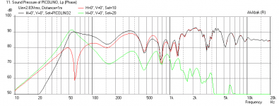
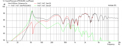
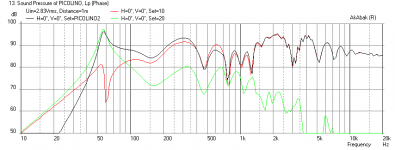
Here is a simulation of the Picolino2 with a 9BGS vs a TC9FD and TG9FD - the BGS is smoother and the TC9 and TG9 have higher Qts so there is a big bass spike - may be a little boomy but not too bad overall.
- 9BGS
- TC9FD
- TG9FD
all 16 in away from back wall.
- 9BGS
- TC9FD
- TG9FD
all 16 in away from back wall.
Attachments
Update on alternative to Vifa 9BGS. It is a unique driver: I have tried many other similar drivers in the sim but nothing works as well - so obviously the Picolino2 is really optimized for this driver. You might try adding a lot of stuffing or use a thinner material for cabinet to help absorb that high Qts bass peak. I tried the following drivers and they all had a bass peak: Visaton FRS8, FR10, Tang Band W3-315e, W3-881si, Fostex FF85WK, Dayton ND-90, Peerless 830986. The TG9FD is probably the closest performer to the original.
It's a fairly straightforward ~20:1 TQWT.
Of the Vifa units, the TG9 is closest if you can't get the design driver. Damped out you'll get the attached (1/2 space). However, what the bald FR sweeps don't tell you & what is often ignored is the rocketing (read 'chronic') harmonic distortion. So beware with the volume knob.
Of the Vifa units, the TG9 is closest if you can't get the design driver. Damped out you'll get the attached (1/2 space). However, what the bald FR sweeps don't tell you & what is often ignored is the rocketing (read 'chronic') harmonic distortion. So beware with the volume knob.
Attachments
Hey, Found is here they should bee in stock. hifisound eShop - VIFA 9 BG 119/8 GLASFASER
Sounds like the TG9FD is the way to go then. My sim actually has all the folds and geometry as shown in the plans (
An externally hosted image should be here but it was not working when we last tested it.
) - I was surprised how "optimized" it was for the 9BGS driver.Wow, thanks for all the information. I appreciate you going to the bother of doing simulations for this. I'll certainly take this all into account when deciding what driver to use.
One question though, what software are you using for the simulations? Is it something someone with nothing more than a reasonable knowledge of computers and basic understanding of transmission line enclosures and speaker parameters could work with?
One question though, what software are you using for the simulations? Is it something someone with nothing more than a reasonable knowledge of computers and basic understanding of transmission line enclosures and speaker parameters could work with?
Hey,
If an easy compact build for a still available full ranger is of interest, maybe this one is for you.
Greetings
no surprise there. Mr Timmermanns a Master of Engineering, has been publishing a diy speaker building magazin here in germany for many years and is know for his very meticulous approach.... I was surprised how "optimized" it was for the 9BGS driver.
If an easy compact build for a still available full ranger is of interest, maybe this one is for you.
Greetings
Last edited:
Sayrum,
Thanks for tip on the coiled up TL. I have designed something similar but a straight MLTL and wall mount. I should be able to sim that no problem. Hey don't know if you remember but it was your post on a flat wall mounted TL that got me into DIY speakers back in Oct of last year.")
X
Thanks for tip on the coiled up TL. I have designed something similar but a straight MLTL and wall mount. I should be able to sim that no problem. Hey don't know if you remember but it was your post on a flat wall mounted TL that got me into DIY speakers back in Oct of last year.
X
Wow, thanks for all the information. I appreciate you going to the bother of doing simulations for this. I'll certainly take this all into account when deciding what driver to use.
One question though, what software are you using for the simulations? Is it something someone with nothing more than a reasonable knowledge of computers and basic understanding of transmission line enclosures and speaker parameters could work with?
I use AkAbak which is a little tough to start but plenty of folks able to help you if you are interested. It has a steep learning curve but is very powerful and can simulate almost any speaker you can imagine including multiple paths, multi arbitrarily placed drivers, horns, TL, band pass, etc. Don Hills has a beginner how to thread for AkAbak that is useful to get started. Other folks use Martin J King's software in Mathcad (aka MJK ), also very good for simulating this sort of stuff but not as flexible as the sheets are "locked".
Good luck.
Hmm, how would the performances of these two units stack up? I could certainly save money by using this other design, and it appears to be an easier build too.Hey,
no surprise there. Mr Timmermanns a Master of Engineering, has been publishing a diy speaker building magazin here in germany for many years and is know for his very meticulous approach.
If an easy compact build for a still available full ranger is of interest, maybe this one is for you.
Greetings
I will get a sim going soon. I imagine that the coiled up one will not be as good but we won't know for sure until I run the sim. KenLBird has made a tapered TL using the FR10 before and reportedly it sounds great. His is a 3 fold box rather than a coil but probably similar performance. It's in the foam core thread.
My sim actually has all the folds and geometry as shown in the plans
At the risk of raining on the self-congratulation -so does mine. I even included some damping.
folks use Martin J King's software in Mathcad (aka MJK ), also very good for simulating this sort of stuff but not as flexible as the sheets are "locked".
Really? About the only back-load the existing sheets can't do are more than 2 vent termini (my heart doth not bleed at the loss), although they could be adapted easily enough.
More generally, all of the popular software available (AJ Horn, AkAbak, Hornrsp, MJK etc.) work with plane-wave assumptions, but that's sufficient for 99.999% of the use expected of it.
Last edited:
Well that's great to hear that the MJK worksheet let's you do what you want. I was under the impression that the heart of the computation formulas were in the "locked down" section to protect MJK's IP. But if you say that is indeed unlocked", then certainly, Mathcad is very flexible and can do whatever you tell it to do.
Parts are, but there's plenty of flexibility to add sections (as many as you like), bends, changes in cross section etc. Doddle. That's what the TL sections sheet for e.g. is for. People like GM, myself & many others have used Martin's worksheets for years (along with AkAbak, Hornrsp etc.) because they're accurate, and as flexible as you need the aforementioned 99.999% of the time. If they weren't, we wouldn't use them.
Last edited:
Hmm, how would the performances of these two units stack up? I could certainly save money by using this other design, and it appears to be an easier build too.
Hey,
i build the coiled tml. If money and availability of the right/correct driver for the design are an issue i vote for the Visaton FR10 in the coiled tml!
From what i read the Piccolino2 might be more detailed and extended in the high frequency but if you are considering building it with a missmatched driver
 not a good idea imo.
There are many different versions of the "pile of small boards" (translated german title of the coiled tml). Here is the sketchup model of all the available versions to download.
You might consider the Vifa 9BN119/8 = Peerless TC9FD-18-08 in this design.
Very simple to build and with the great little (+ inexpensive) driver the best bang for your buck imo!
But it does need mounting on a wall or other large flat surface (baffle step).
Thanks xrk971Sayrum,
Thanks for tip on the coiled up TL. I have designed something similar but a straight MLTL and wall mount. I should be able to sim that no problem. Hey don't know if you remember but it was your post on a flat wall mounted TL that got me into DIY speakers back in Oct of last year.
X
I´m glad to be of service. I must admit that i still can´t interpret the Akabak graphs totaly
cheers
Last edited:
If an easy compact build for a still available full ranger is of interest, maybe this one is for you.
Greetings
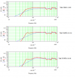
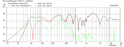
Here is the sim of the "Pile of Boards" or "coiled TL" as I call it. It actually looks pretty nice - and has good bass response down to 50 Hz for the very inexpensive FR10 driver. I put stuffing to damp HF up to the 3 turn (the turn from vertical downwards to the right after the driver).
The sim used the dimensions from this plan (with 100 mm width of TL channel):

Plots:
- Freq response for speaker placed 8 in away from back wall mic at 1 m
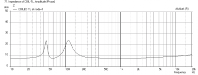
- Impedance
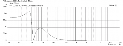
- Driver cone displacement
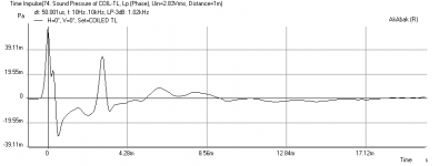
- Impulse response
Summary: a well-balanced enclosure with good bass, well controlled cone movement, decent impulse response for OK group delay.
Attachments
I must admit that i still can´t interpret the Akabak graphs totaly
cheers
The freq response curve is SPL vs frequency (the distance the mic is at is in the graph legend) and the black curve is the overall output, the red is the driver direct sound radiated, the green is typically the vent/horn output only.
The next plots typically are the electrical impedance of the driver, the driver cone displacement in mm vs freq, then sometimes I show the impulse response which gives you an idea of the group delay - you want to make sure that the main secondary pulse is < 8 ms otherwise there will be very noticeable time delay effects from say, a kick drum sound, happening way after the initial punch from the direct radiator.
Hope that helps.
- Status
- This old topic is closed. If you want to reopen this topic, contact a moderator using the "Report Post" button.
- Home
- Loudspeakers
- Full Range
- Vifa 9 BGS 119/8 Alternative for Picolino 2