Project Conception  (the teaser
  )
)
Last winter I had some fun using foam core board to build a couple of speakers after reading XRK971’s threads--a Cornu spiral horn using Fostex FE108eS and a little FH3 inspired design using Vifa TC9FD. I found the Cornu horn fatally flawed (for my taste) due to a suck-out in the 100-200 Hz region. The other one with the little 3.5” Vifa was a surprising success: while limited in SPL, it had remarkable bass extension and a sonic presentation similar to a Metronome. I love Mets. I’ve built four pairs of them now.
So as I was plotting my summer build, I knew I wanted a driver larger than the ones I have been using lately; maybe an 8” again. Haven’t used an 8” since I made the Half Changs with FE206e for the kids a few years back. Thought about the FE208eS in a BIB. Then financial considerations pointed toward a less costly option. How about the recently released FF225wk?
I consulted with SWMBO. Not another Met. Maybe a bit smaller than a BIB. Definitely a different veneer--she’s had enough of red oak.
Thinking back to the FH3 inspired Vifa build, I felt that it had a sonic presentation similar to a Met. And isn’t it something like a Met folded in half? maybe... Some years ago when I started building speakers as a way to while away the hours in retirement, I didn’t intend to get involved with design. Then along came MJK, who began to mentor me. Since I lack the creativity to come up with a radically new design, all I can do is mess with prior designs. Some of the ideas are new(er), and (many) other designs date back to the early years of audio. So I started with Martin’s MLTL worksheet, then moved on to his TL sections worksheet.
This design is intended to fulfill my goals: a larger sonic image on orchestral music than the 4 to 4.5” drivers I have used; able to produce 90 dB SPL peaks on orchestral music without getting congested; able to provide an authoritative presentation in the 60 to 120 Hz octave. So it’s not the last word in bass extension; not going to make your ears bleed, but plenty loud for me-- loud enough that I couldn’t have a conversation without shouting.
I showed Martin what I was working on. While I was making progress, it was slow going, making the multitude of changes in the TL worksheet to optimize the design. Martin took pity on me. He knew I was after a specific TL configuration, so he made a custom worksheet for me; with this sheet, all I have to do is define the basic cabinet geometry, then the worksheet calculates the sections automatically for both the basic model in the first half of the worksheet AND the more complicated second half of the sheet which incorporates the details of cabinet geometry as well as room boundary effects. I can now run dozens of simulations with only a few minutes of work on my part!
to be continued....
(the teaser )Last winter I had some fun using foam core board to build a couple of speakers after reading XRK971’s threads--a Cornu spiral horn using Fostex FE108eS and a little FH3 inspired design using Vifa TC9FD. I found the Cornu horn fatally flawed (for my taste) due to a suck-out in the 100-200 Hz region. The other one with the little 3.5” Vifa was a surprising success: while limited in SPL, it had remarkable bass extension and a sonic presentation similar to a Metronome. I love Mets. I’ve built four pairs of them now.
So as I was plotting my summer build, I knew I wanted a driver larger than the ones I have been using lately; maybe an 8” again. Haven’t used an 8” since I made the Half Changs with FE206e for the kids a few years back. Thought about the FE208eS in a BIB. Then financial considerations pointed toward a less costly option. How about the recently released FF225wk?
I consulted with SWMBO. Not another Met. Maybe a bit smaller than a BIB. Definitely a different veneer--she’s had enough of red oak.
Thinking back to the FH3 inspired Vifa build, I felt that it had a sonic presentation similar to a Met. And isn’t it something like a Met folded in half? maybe... Some years ago when I started building speakers as a way to while away the hours in retirement, I didn’t intend to get involved with design. Then along came MJK, who began to mentor me. Since I lack the creativity to come up with a radically new design, all I can do is mess with prior designs. Some of the ideas are new(er), and (many) other designs date back to the early years of audio. So I started with Martin’s MLTL worksheet, then moved on to his TL sections worksheet.
This design is intended to fulfill my goals: a larger sonic image on orchestral music than the 4 to 4.5” drivers I have used; able to produce 90 dB SPL peaks on orchestral music without getting congested; able to provide an authoritative presentation in the 60 to 120 Hz octave. So it’s not the last word in bass extension; not going to make your ears bleed, but plenty loud for me-- loud enough that I couldn’t have a conversation without shouting.
I showed Martin what I was working on. While I was making progress, it was slow going, making the multitude of changes in the TL worksheet to optimize the design. Martin took pity on me. He knew I was after a specific TL configuration, so he made a custom worksheet for me; with this sheet, all I have to do is define the basic cabinet geometry, then the worksheet calculates the sections automatically for both the basic model in the first half of the worksheet AND the more complicated second half of the sheet which incorporates the details of cabinet geometry as well as room boundary effects. I can now run dozens of simulations with only a few minutes of work on my part!
to be continued....
The design is an expanding TL with a very slight constriction just before the terminus. Looking at the design and how it behaves in simulations (and discussing it with Martin), I am quite sure that this is a TL, not a horn. The ‘mouth’ (which I am taking as the 8” tall x 10” wide constriction) simply isn’t large enough to act as a horn in the bass frequency range. Hence the name: Pappa’s TL.
With that introduction let me say that despite superficial appearances:
This design is NOT a Frugal Horn! It is not endorsed by either Scottmoose or Dave @ P-10. They have resisted calls to release designs for a Frugal-Horn using larger drivers. Having worked through a similar design, I can see why: the cabinet gets big & clunky AND the low freq extension isn’t what most folks would expect-- at least not with the cabinet size & bass alignment I want to use. While you can push the tuning lower in a moderately large cabinet, you end up needing significant EQ to get the bass SPL to match up with the level of the mids & highs--then you have problems running up against Xmax. Of course, if you want a really huge box, then deeper bass becomes a possibility. Just plug the numbers for the FF225wk into the BIB calculator...
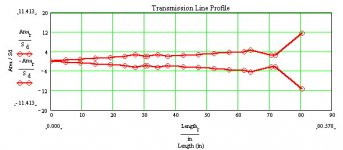
Shown below are the TL profile from MathCAD and a diagram of design:
to be continued....
With that introduction let me say that despite superficial appearances:
This design is NOT a Frugal Horn! It is not endorsed by either Scottmoose or Dave @ P-10. They have resisted calls to release designs for a Frugal-Horn using larger drivers. Having worked through a similar design, I can see why: the cabinet gets big & clunky AND the low freq extension isn’t what most folks would expect-- at least not with the cabinet size & bass alignment I want to use. While you can push the tuning lower in a moderately large cabinet, you end up needing significant EQ to get the bass SPL to match up with the level of the mids & highs--then you have problems running up against Xmax. Of course, if you want a really huge box, then deeper bass becomes a possibility. Just plug the numbers for the FF225wk into the BIB calculator...
Shown below are the TL profile from MathCAD and a diagram of design:
to be continued....
Attachments
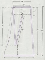
Forgot to mention in the last post that the enclosure is 10” wide internal, so with 3/4” ply the box is 11.5” wide external.
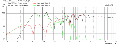
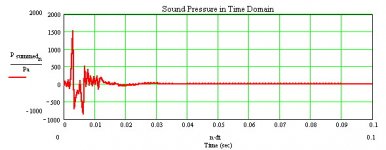
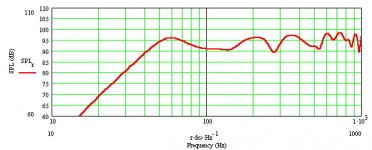
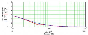
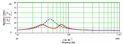
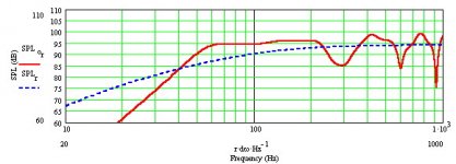
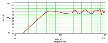
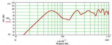
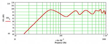
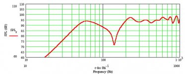
And now: Here are some of the graphs from MJK’s MathCAD simulation of Pappa’s TL.
You may note that the TL is tuned to 54 Hz, despite the FF225wk having an F(s) of 44 Hz. As mentioned previously, if you tune lower without making the enclosure larger, then the SPL drops at low frequencies. My preference is to keep the box more modest in size and give up some bass extension. Hoffman’s Iron Law in action.
And before anyone asks: don’t bother putting other drivers into this cabinet, the results will most likely be disappointing. The only one I checked which wouldn’t fall on its face is the F200A--it would sound OK, but should really be put in a cabinet tuned to get the most from it rather than settling for merely OK. The FE206en and FE208eS don’t work.
Measurements will be coming, but at the moment things are a bit busy. After Labor Day, Martin will bring his PE Omni-Mic over & have a listen.
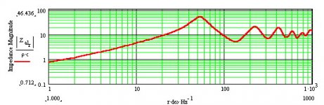
Graphs:
-- acoustic impedance
-- SPL (from top of worksheet)
-- electrical impedance
-- woofer displacement
-- in-room SPL
-- impulse response
to be continued...
And now: Here are some of the graphs from MJK’s MathCAD simulation of Pappa’s TL.
You may note that the TL is tuned to 54 Hz, despite the FF225wk having an F(s) of 44 Hz. As mentioned previously, if you tune lower without making the enclosure larger, then the SPL drops at low frequencies. My preference is to keep the box more modest in size and give up some bass extension. Hoffman’s Iron Law in action.
And before anyone asks: don’t bother putting other drivers into this cabinet, the results will most likely be disappointing. The only one I checked which wouldn’t fall on its face is the F200A--it would sound OK, but should really be put in a cabinet tuned to get the most from it rather than settling for merely OK. The FE206en and FE208eS don’t work.
Measurements will be coming, but at the moment things are a bit busy. After Labor Day, Martin will bring his PE Omni-Mic over & have a listen.
Graphs:
-- acoustic impedance
-- SPL (from top of worksheet)
-- electrical impedance
-- woofer displacement
-- in-room SPL
-- impulse response
to be continued...
Attachments
Nice work there Jim. So it sounds like you have actually built it? AkAbak came up with the same tuning freq and I like how you are keeping the SPL high rather than push for low extension - 54 Hz is good for most music. Placement from wall seems to be a critical factor. How far back is the wall in your in room simulation?
So MJK will be dropping by. You live in an alternate reality.
Ain't that the truth
Or it means Jim lives somewhere near NY or NJ?Side bar--
Simulating boundary loading:
We all know that rooms have a profound affect on how speakers sound. And thus we spend lots of time fiddling with speaker (and furniture) placement, optimizing things as best we can. I have felt that rooms with cathedral ceilings sound better than rooms with standard 8’ ceilings. Using Martin’s MathCAD worksheets, I can see at least part of what is going on.
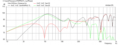
The graphs below are from the second part of the worksheets. Speaker positioned as follows:
Distance from Room Corner of Baffle Center= 36”
Angular Position from Room Corner of Baffle Center= 45 deg.
Rotation of Baffle Towards Room Center= 35 deg.
SPL curves are shown for:
walls but no floor & no ceiling
walls & floor but no ceiling
walls, floor & 8’ ceiling
walls, floor & 10’ ceiling
There is no option for a slanted ceiling, but I think the sloping of a cathedral ceiling is beneficial. But I could be wrong... Whatever, I think the graphs show that having the ceiling a bit higher is better.
to be continued...
Simulating boundary loading:
We all know that rooms have a profound affect on how speakers sound. And thus we spend lots of time fiddling with speaker (and furniture) placement, optimizing things as best we can. I have felt that rooms with cathedral ceilings sound better than rooms with standard 8’ ceilings. Using Martin’s MathCAD worksheets, I can see at least part of what is going on.
The graphs below are from the second part of the worksheets. Speaker positioned as follows:
Distance from Room Corner of Baffle Center= 36”
Angular Position from Room Corner of Baffle Center= 45 deg.
Rotation of Baffle Towards Room Center= 35 deg.
SPL curves are shown for:
walls but no floor & no ceiling
walls & floor but no ceiling
walls, floor & 8’ ceiling
walls, floor & 10’ ceiling
There is no option for a slanted ceiling, but I think the sloping of a cathedral ceiling is beneficial. But I could be wrong... Whatever, I think the graphs show that having the ceiling a bit higher is better.
to be continued...
Attachments
Right, ideally a room should have all walls expanding from the sound wall to minimize its Eigenmodes and 'slap' echo. The one room I built this way [converted half basement actually] combined a diffusor back wall in the form of a sloped 'peak' similar to the attached link was the next best thing to ~2pi outdoors with a pair of corner loaded, heavily modified Altec A7-500 small cinema speakers.
20,000 Watt Home Hi-Fi System
GM
20,000 Watt Home Hi-Fi System
GM
Side bar--
Simulating boundary loading:
We all know that rooms have a profound affect on how speakers sound. And thus we spend lots of time fiddling with speaker (and furniture) placement, optimizing things as best we can. I have felt that rooms with cathedral ceilings sound better than rooms with standard 8’ ceilings. Using Martin’s MathCAD worksheets, I can see at least part of what is going on.
The graphs below are from the second part of the worksheets. Speaker positioned as follows:
Distance from Room Corner of Baffle Center= 36”
Angular Position from Room Corner of Baffle Center= 45 deg.
Rotation of Baffle Towards Room Center= 35 deg.
SPL curves are shown for:
walls but no floor & no ceiling
walls & floor but no ceiling
walls, floor & 8’ ceiling
walls, floor & 10’ ceiling
There is no option for a slanted ceiling, but I think the sloping of a cathedral ceiling is beneficial. But I could be wrong... Whatever, I think the graphs show that having the ceiling a bit higher is better.
to be continued...
Here is what I get for a corner placement at 36 in from walls and 35 deg toe-in. Looks very similar - I just can't get the damping to smooth out like the MJK.
Attachments
Satisfied that I have a design which will meet my goals, I ordered a pair of FF225wk. I also ordered a pair of Eminence APT-80 horn tweeters, as the FF225wk is reported to need help in the top octave. I put the FF225wk into cardboard boxes to break them in. They sounded very promising to me. Then my wife commented,”They sound so good already in the cardboard boxes, I can’t wait to hear what they sound like in proper cabinets.” Unsolicited support from SWMBO-- Oh yea, this is gonna be good!
Time to proceed--cautiously!
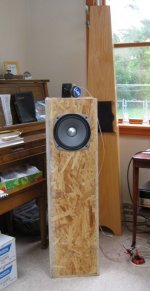
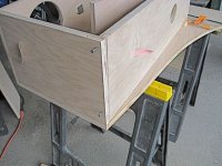
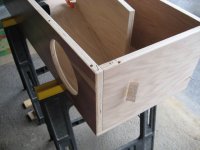
With a Met, I know what I’ll get. With this design, I was less certain, so I built a prototype in oriented strand board. OSB is cheap, both in terms of cost and quality. When this project is finished, I will have no qualms about tossing this ugly thing into the trash.
I usually spend about 2 months building a pair of speakers. I obsess about every detail of fit & finish. Not that I can produce anything close to the furniture quality cabinets of someone like Terry Cain, but I want it to be the very best I can make. Using crummy OSB, I saw no point in worrying about appearance: just cut the wood & glue it together. Why waste time cutting another piece of OSB just so that the bottom board extends all the way to the back of the side extensions? The piece that’s an inch short will work just fine for test purposes. Curvy bit on the sides like the FH3 is esthetically pleasing, but not worth it here. My one concession in this regard was sanding the edges & corners so that I wouldn’t get splinters every time I got near it. Even so, I don’t want to try moving it around without gloves. I’ll say it again: ugly, ugly, ugly! So, less than a week from start to completed speaker. From the front, it doesn’t look too imposing. But from the side, it’s a different story: this one hefty chunk of speaker!
I stuffed the first third of the line with Parts Express Acousta-Stuf. To prevent reflections from sides, back & top, I lined the areas near the driver with 1.5” egg-crate foam from PE. Mounted the driver & gave it a listen. Not bad, but needs BSC. Calculator says 1 mH inductor and 2.5 ohms for 3 dB correction. I settled on 1 mH and 2.2 ohms. Listen again: nice! Except that cymbals sound dull/muffled. Of course I knew this would be the case; both from comments about the FF225wk and because I had been breaking them in in cardboard boxes for 220 hrs.
Time to add the Eminence APT-80 tweeters. The tweeter will be mounted in a separate box on top. This arrangement provides maximum flexibility: it can be facing the front wall or corner--as recommended by Bob Brines (and similar to other designs like Terry Cain’s Super Abby). Or it could point toward the ceiling. Maybe even face the listener. During testing, I found that not all recordings are created equal: most sounded better with the tweeter facing away from the listener, while a few were better with the tweeter aimed toward the listener. And if you move the speaker around, then the tweeter might do better if positioned at a different angle. With the tweeter in a separate box, it’s a tweeker’s dream!
I couldn’t find an impedance plot for the APT-80, so I am basing my calculations on its nominal impedance of 8 ohms. With a specified sensitivity of 106 dB, I guessed at a 0.47 uf capacitor, which should yield an XO point of 41 KHz. Connect it up & listen again: not bad, but not quite enough on some recordings. I haven’t settled on a final value; it’s a toss-up between 0.47 and 0.69 uf. If I change my mind, it’s no problem to tweek it, since it’s in the tweeter’s enclosure up top and easily accessible.
For evaluation during extended listening, I put the FF225wk on the left channel and one of my FE167e Mets on the right channel. Result? Completely satisfied. Goals have been met, yea, exceeded! Large scale orchestral music sounds very good; sounds... well, large; doesn’t get congested and can produce 90+ dB peaks with no problem. What’s more, the bass has more extension than I expected. Using Stereophile’s test CD and my trusty RS SPL meter, I get an F10 of about 40 Hz at the listening position, thanks in part to room reinforcement. I thought I would need to get down to 30 Hz for a satisfying experience, but so far, I haven’t felt the need of a sub.
And what does SWMBO think? She describes the sound as sweet. Yes, it’s bit clunky, but it’s tolerable. Verdict: time to go buy plywood and order veneer!
to be continued....
Time to proceed--cautiously!
With a Met, I know what I’ll get. With this design, I was less certain, so I built a prototype in oriented strand board. OSB is cheap, both in terms of cost and quality. When this project is finished, I will have no qualms about tossing this ugly thing into the trash.
I usually spend about 2 months building a pair of speakers. I obsess about every detail of fit & finish. Not that I can produce anything close to the furniture quality cabinets of someone like Terry Cain, but I want it to be the very best I can make. Using crummy OSB, I saw no point in worrying about appearance: just cut the wood & glue it together. Why waste time cutting another piece of OSB just so that the bottom board extends all the way to the back of the side extensions? The piece that’s an inch short will work just fine for test purposes. Curvy bit on the sides like the FH3 is esthetically pleasing, but not worth it here. My one concession in this regard was sanding the edges & corners so that I wouldn’t get splinters every time I got near it. Even so, I don’t want to try moving it around without gloves. I’ll say it again: ugly, ugly, ugly! So, less than a week from start to completed speaker. From the front, it doesn’t look too imposing. But from the side, it’s a different story: this one hefty chunk of speaker!
I stuffed the first third of the line with Parts Express Acousta-Stuf. To prevent reflections from sides, back & top, I lined the areas near the driver with 1.5” egg-crate foam from PE. Mounted the driver & gave it a listen. Not bad, but needs BSC. Calculator says 1 mH inductor and 2.5 ohms for 3 dB correction. I settled on 1 mH and 2.2 ohms. Listen again: nice! Except that cymbals sound dull/muffled. Of course I knew this would be the case; both from comments about the FF225wk and because I had been breaking them in in cardboard boxes for 220 hrs.
Time to add the Eminence APT-80 tweeters. The tweeter will be mounted in a separate box on top. This arrangement provides maximum flexibility: it can be facing the front wall or corner--as recommended by Bob Brines (and similar to other designs like Terry Cain’s Super Abby). Or it could point toward the ceiling. Maybe even face the listener. During testing, I found that not all recordings are created equal: most sounded better with the tweeter facing away from the listener, while a few were better with the tweeter aimed toward the listener. And if you move the speaker around, then the tweeter might do better if positioned at a different angle. With the tweeter in a separate box, it’s a tweeker’s dream!
I couldn’t find an impedance plot for the APT-80, so I am basing my calculations on its nominal impedance of 8 ohms. With a specified sensitivity of 106 dB, I guessed at a 0.47 uf capacitor, which should yield an XO point of 41 KHz. Connect it up & listen again: not bad, but not quite enough on some recordings. I haven’t settled on a final value; it’s a toss-up between 0.47 and 0.69 uf. If I change my mind, it’s no problem to tweek it, since it’s in the tweeter’s enclosure up top and easily accessible.
For evaluation during extended listening, I put the FF225wk on the left channel and one of my FE167e Mets on the right channel. Result? Completely satisfied. Goals have been met, yea, exceeded! Large scale orchestral music sounds very good; sounds... well, large; doesn’t get congested and can produce 90+ dB peaks with no problem. What’s more, the bass has more extension than I expected. Using Stereophile’s test CD and my trusty RS SPL meter, I get an F10 of about 40 Hz at the listening position, thanks in part to room reinforcement. I thought I would need to get down to 30 Hz for a satisfying experience, but so far, I haven’t felt the need of a sub.
And what does SWMBO think? She describes the sound as sweet. Yes, it’s bit clunky, but it’s tolerable. Verdict: time to go buy plywood and order veneer!
to be continued....
Attachments
Very nice work Jim! Congrats on a successful speaker from scratch. OSB actually has a nice industrial look if you are into that.

Hi X,
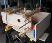
There will be some side shots of the plywood build. And shots of the internals during build!
The cap on the tweeter is set to XO at 41KHz so that its level is down to match the 225 around 8 KHz. The alternative is to pad down the tweeter with a resister along with the cap.
Cheers, Jim
So I purchased two sheets of 3/4” plywood from Curtis Lumber. (The local Home Depot & Lowes don’t have any 3/4” ply that I want to buy--too many voids, not flat, and/or just plain beaten up.)
The curved edge on the rear of the side pieces was done by having my wife sketch the curve on one piece; then I used a jig saw to cut it as well as I could. Sand paper and elbow grease smoothed the curve. That first piece was used to replicate the other three side pieces; after rough cutting with the jig saw, they were cut to final shape with a router & a pattern follower bit.
I mostly build using dowel pins (for alignment) and clamps. In this build, there are a couple points where I reverted back to screws (for alignment and hold) or 17 gauage wire brads slipped into 1/16” pilot holes (for alignment).
The back/divider board joint was done by cutting the divider slightly short, then making a suitably angled flat spot on the bottom edge with a sanding block. When clamped together with an abundance of wood glue, the result is a nice tight ‘V’ joint.
to be continued...
Attachments
- Status
- This old topic is closed. If you want to reopen this topic, contact a moderator using the "Report Post" button.
- Home
- Loudspeakers
- Full Range
- Pappa's TL