Francisco,
Fantastic job there - the first mini Karlsonators I know of made out of all wood! Beautiful. They do indeed sound better on the floor - they were designed for floor placement. The highs will be just a little less than the Cornus since there is the Karlson aperture, but you make up for it in wider uniform directivty and deeper bass and more mid-bass. It makes a difference to fully screw or glue the front K-aperture on - you won't know the true sound until you do. The sounds in recordings you now hear are all the sounds you have been missing! It makes a lot of live recordings sound like you are in the room because you can hear all the sounds like feet shuffling on the stage, fingernails scratching on the wire wound strings of a bass as the hand moves up and down, etc. It's amazing that the little 3110 amp and a four 3.5 inch drivers can fill up a 5x6 meter room.


Regards,
X
Fantastic job there - the first mini Karlsonators I know of made out of all wood! Beautiful. They do indeed sound better on the floor - they were designed for floor placement. The highs will be just a little less than the Cornus since there is the Karlson aperture, but you make up for it in wider uniform directivty and deeper bass and more mid-bass. It makes a difference to fully screw or glue the front K-aperture on - you won't know the true sound until you do. The sounds in recordings you now hear are all the sounds you have been missing! It makes a lot of live recordings sound like you are in the room because you can hear all the sounds like feet shuffling on the stage, fingernails scratching on the wire wound strings of a bass as the hand moves up and down, etc. It's amazing that the little 3110 amp and a four 3.5 inch drivers can fill up a 5x6 meter room.
Regards,
X
Glad to hear I'm the first one building them!! Yes you're right, it's like actually being on stage.
Your comment about the front K-aperture encourages me to finish the speakers as soon as possible, do you think it is a good idea to use speaker gasket strips and nails/screws to seal it? I'm a little concerned that without the speaker gasket the front K-aperture won't be completely sealed, but I don't know if it would be a good idea to use that as a sealing material.
Thanks X! I'm really happy with the result, this was a cheap project ( even cheaper for you people living in the US ) and compared to the Cornus it was like shooting fish in a barrel !! The results already exceeded my expectations, can hardly wait to definitely close the speakers and hear the difference!!
Cheers,
Fran
Well that was uneventful,
(my post is nowhere to be found.)
Update,
Still working on the speaker, had to get some more parts.
Also need some more white foam,
have a black foam spare, maybe for the bottom, back, and top.
I almost was thinking about using it for the sound board.
Question - Drivers Looking at it I don't think the tweeter will sound so good
on the top board (board above the driver).
I'm thinking of sliding the mid/bass up or down and thinking tweeter would
disburse better on the bottom with the mid/bass on top.
Then, this would misalign the time...maybe slurring the sound somewhat?
Better to place tweet above mid bass now wonder how much the wings will
direct it?
However, I wonder if I make a bracket and can mount above the inverted dust
cap of the mid/bass driver.
Now I'm thinking that I should have just done the cab in wood to begin with.
NOTES:
My mid/bass drivers weigh in at over 2 lbs each.
This will pull apart the speaker eventually with use.
The hot melt glue I have isn't the best stuff on earth,
wondering how epoxy would do?
Hot melt is definitely pretty quick. Have something like
Masonite that I'll back the driver sound board with.
Then make a triangle brace for the side and bottom.
It doesn't need to be solid I think, but like a triange
it will hold up well.
For holding pieces and fitting I use double sided tape.
Like double sided celophane tape, then when fitting
parts I glue in the alignment/brace foam pieces.
Havent't fitted the masonite yet.
Use a wood supra baffle if your driver weighs 2 lbs. or use all wood on front baffle. The hot melt is key for tacking pieces I n place while you hold it by hand to set. You can add more PVA over the hot melt tack or epoxy but I don't think you need it. Don't worry about time alignment of tweeter and woofer. You won't hear difference in 2 in path.
This had proved more "challenging" to me that I though possible.
I should have just purchased a full range driver.
That said, trying to cut a 5.5-inch straight panel
prooved even more challenging.
It would have only taken 5 -10 mins tops if I had a 1/2 decent table saw.
I don't.
I have a POS Craftsman 9 inch band saw.
The saw speaks of Chinese designers not having a slight
understanding of what they are building/designiing.
Nothing is stable in it, so when you go to cut,
well you guessed it, once it loads, you get wobble
cut and off into the never never land you go.
I finally ended up cutting the rectangle face with
a skill saw. Which presents it own set of challenges.
Ah, but for the love of the foam...
Pics are still coming sometime soon.
The wooden piece probably did not have to be flat edged of square if you glue it on top of the foam core. But it does suck to have non cooperative floppy tools. A bandsaw would normally be fine if the guide rail is stiff enough.
x, not sure what the guide is called. It is adjustable depending on
the thickness of the cut. So I asjust it abot 1/8 inch, tightening it
down start cutting and 20 degrees cut happens board wont
push through??? The guide drops down and blocks the wood,
then of course the cheap tube rails give up another 1/8 to 1/4 inch
turn on the wood piece.
Investigate, raise the guide try a few more time, same thing.
Tighten it again...
X, you know I'm really going to be p***ed off it my little butget
prototypes dont sound good. arrrrg. : O)
The whole guide structure is junk, one metal bolk with two plastic
nuts, one for raising and lowering the guide, one for tightening the
guide. Doesn't matter, you sturn on the machine and the guide
comes back down.
Now what does the guilde look like?
Think of the the sewing maching foot, which holds down the fabric.
Well the chinese in their brilliance, moiunted the foot, off by 90 degrees
So instread of whn you are pushing your board through to be cut and it
holding it down smoothly.....you hit the side of the foot and get stuck.
Pics on the six o'clock new folks, I promise.
I think one of the old folks homes around here has a table saw....
Thank you gentleman for yor patience wth me. I get cranky when I'm
trihg to do something "right" and I have to rig up ways to be mediocher(sp)
at best.
On the good side is my little helper, she keeps me in smiles.
Last edited:
Finally got the pics developed, as promised.
Earlier than 6 O'clock news.
Layout
Layout2
Assistant
Assistant with measuring device, big
Assistant with writing device
Assistant measuring
Assistant marking the measurement
Assistant drawing the measurement
Exacto sharpen, no assistant
Layout before cut
Draw on board before cut
Ensure to scale
Check before cut
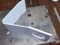
Prototype after initial cut and fit
Prototype rear fit
Earlier than 6 O'clock news.
Layout
An externally hosted image should be here but it was not working when we last tested it.
Layout2
An externally hosted image should be here but it was not working when we last tested it.
Assistant
An externally hosted image should be here but it was not working when we last tested it.
Assistant with measuring device, big
An externally hosted image should be here but it was not working when we last tested it.
Assistant with writing device
An externally hosted image should be here but it was not working when we last tested it.
Assistant measuring
An externally hosted image should be here but it was not working when we last tested it.
Assistant marking the measurement
An externally hosted image should be here but it was not working when we last tested it.
Assistant drawing the measurement
An externally hosted image should be here but it was not working when we last tested it.
Exacto sharpen, no assistant
An externally hosted image should be here but it was not working when we last tested it.
Layout before cut
An externally hosted image should be here but it was not working when we last tested it.
Draw on board before cut
An externally hosted image should be here but it was not working when we last tested it.
Ensure to scale
An externally hosted image should be here but it was not working when we last tested it.
Check before cut
An externally hosted image should be here but it was not working when we last tested it.
Prototype after initial cut and fit
An externally hosted image should be here but it was not working when we last tested it.
Prototype rear fit
An externally hosted image should be here but it was not working when we last tested it.
Sync,
Nice work! You are very careful laying it out. I am a bit more sloppy in that I cut a long strip and then chop it up at the correct lengths (based on the sketch on the side panel) to form the internal channels. Then I glue it to the hand sketch on a sidewall with key points measured with a ruler but never a drafting ruler or T square and protractors. Grandcalmar has found that using a long strip and creasing and bending at corners provides a nice contiguous channel. I think this may be the way to go. You actually chemically developed the photos? Wow, I haven't touched a film camera in years (and I have some nice ones). Keep up the great progress. You are close to first sound.
Nice work! You are very careful laying it out. I am a bit more sloppy in that I cut a long strip and then chop it up at the correct lengths (based on the sketch on the side panel) to form the internal channels. Then I glue it to the hand sketch on a sidewall with key points measured with a ruler but never a drafting ruler or T square and protractors. Grandcalmar has found that using a long strip and creasing and bending at corners provides a nice contiguous channel. I think this may be the way to go. You actually chemically developed the photos? Wow, I haven't touched a film camera in years (and I have some nice ones). Keep up the great progress. You are close to first sound.
X, Freddi, anyone,
Just a quick question on the WAF for the K models. Is it possible to put the vent so it opens upward (ie: turn the K upside down). I realise this would mean a modification to the angle of the baffle, but might look better. Just wondering if any one has tried this and can comment on the sound.
Just a quick question on the WAF for the K models. Is it possible to put the vent so it opens upward (ie: turn the K upside down). I realise this would mean a modification to the angle of the baffle, but might look better. Just wondering if any one has tried this and can comment on the sound.
It works, less bass extension and less bass amplitude due to less floor loading. It works and sounds pretty nice though. You can't really change the angle because that is integral to the mouth and the K-aperture. Mount high (7 ft) and have it aim down. Or put grill cloth on the whole thing and problem solved.
X,
The next pints on me.
Processing film is my little joke for taking so long
to post the pics, please take no offense.
Yeah I have a nice film camera that is kind of in forever storage now.
I have the fit right I think. I have to find a way to cut the little
wood panels to mount the speakers, and panels for the back to
mount the binding posts. I guess I can drill and
hand held saber saw it. I just don't want my little prototype
to shake all apart.
I think I do the same, after I drew it on the sheets, I cut
smaller strips for the mounting points. I used double tape
to hold them, then test fitted and glued in the tabs (for lack
of a better word).
I'm kind of doing what Grandcalmar is doing I think but I
scored the the bends with Xacto, then split the board.
My thought was then I will hot melt glue alaong the
the seam which I scored (or split) so no air leaks
out and provides support. The other side of the
score has the paper intact, it is just bent.
FYI - I could not figure out a way to draw the
speaker cut out w/o a compass. It is actually
a childs compass, but it works what can i say.
The kid was crying because I took it from her.
I'm a mean ol' guy.
AND
If you look at the second pic, I withheld my
assistance baby bottle until she got to work
and drew out to scale on the panels.
I'll be in hot water with the labor relations
board, so please don't tell anyone.
I ended up not using the drafting t-square because
many years ago it lost a screw and it wobbles just
enough to not be square.
I've not been able to find a replacement screw.
it is something like a #2 or #4 beveled philips
about 1/8 inch.
Considering someone who has great distain for
wobbly tools I sure do have a collection of them.
For some reason they seem to migrate to me, go figure?
AND
I actually have a couple of nice wood panels that
would make a good looking speakers based on the
foam prototypes. They are thin 1/8 plywood, that could
be dampened and braces internally. Might sound okay too.
First I need to finish my foam jobs.
Thanks everyone for your support.
Post Script - I didn't know how to get the formula/function
that you has posted X, so I found pic with the nubers on
it and then tried to scale it.
I have the expo0nential slot running the length of the speaker
but and am now thinking maybe it should be around 2/3s the
length. Some of the hybred speakers seem to have the
slot not even covering the speaker but are only on
the the ported side of the cabinet.
You actually chemically developed the photos? Wow, I haven't touched a film camera in years (and I have some nice ones).
Last edited:
I find convenient round household objects with the same diameter as my driver cutout and use that to draw the circle to cut. For the Vifa it is the inside of a standard 3 in dia roll of packing tape. For the 6.6 inch woofers, it is a Williams Sonoma China soup bowl - which also doubles as the sharpening stone for the xacto on the bottom rim (don't tell my wife).
That's pretty good X...thanks for the suggestions.
Sometimes I think too much in the box.
Cups, bowls, glasses, I"ll never look at
them the same again.
...and the wife will never let me hear the end of it either.
I got some rather nice sharpening stones when
I was last in Arkansas. I got the biggest one's
they had because I hate running out of room
esp with a knife. They are all about 10" x 3".
If I could find some about 24" x 8" it would
make me a happy camper.
Last edited:
Hi X- I have started work on the Mini K using the sizing you recomended:
The W3-881SJF sims very nicely in a 0.4x in height and depth and 0.33x in width.
My dimensions are 11.75x 6.125x 4.5 inside dimensions. Does that seem about right to you? I'm concerned that the width is so narrow.
cheers
The W3-881SJF sims very nicely in a 0.4x in height and depth and 0.33x in width.
My dimensions are 11.75x 6.125x 4.5 inside dimensions. Does that seem about right to you? I'm concerned that the width is so narrow.
cheers
Hi X- I have started work on the Mini K using the sizing you recomended:
The W3-881SJF sims very nicely in a 0.4x in height and depth and 0.33x in width.
My dimensions are 11.75x 6.125x 4.5 inside dimensions. Does that seem about right to you? I'm concerned that the width is so narrow.
cheers
That sounds about right, you can make it 5 in wide without too much of a problem if you want it wider.
I'm kind of doing what Grandcalmar is doing I think but I
scored the the bends with Xacto, then split the board.
My thought was then I will hot melt glue alaong the
the seam which I scored (or split) so no air leaks
out and provides support. The other side of the
score has the paper intact, it is just bent.
For bends I cut the top layer of paper and only part way into the foam and then bend the board with the cut on the inside of the bend. I find there is no need to add hot glue - the bend is airtight. To make the double thick baffle I do the opposite and bend away from the cut which completely severs the foam but leaves the inside paper intact, making it easy to line up the two pieces (I then join these with a simple glue stick). Using this technique the innards of a 0.4X mini Karlsonator can be formed from one piece of FC with just bends and no hot glue.
Cheers!
Attachments
- Home
- Loudspeakers
- Full Range
- Mini Karlsonator (0.53X) with Dual TC9FDs