I'd like to see that too as I have AN8 stamped frame - - -Greg B's Karlsonator 8 seems like it would be a good size vs the Karlsonator 12
Karlsonator8 plan https://plus.google.com/photos/1005...5685712049966245090&oid=100545049816297868412
Karlsonator8 plan https://plus.google.com/photos/1005...5685712049966245090&oid=100545049816297868412
Freddi,
Looking at overall dimensions, it seems that the smaller SKx's are scaled down Karlsonators to first order. Rather than re-enter the entire geometry of an SK8, or SK6.5 I think it will be sufficient to scale down the 12 in K'nator. I have added ability to scale top channel vent and back chamber volume independently so there is flexibility there. I typically play with those to tune the response with any given driver to get as deep and flat as possible. I will run the AN Super 8 as soon as I get to my computer again.
X
Just FYI, the Karlsonator 8 is slightly 'higher aspect' than the full size Karlsonator. This worked out a little better in my sims, using the FE206EN for the driver.
The Karlsonator 6 is more or less scaled down proportionally from the Karlsonator (12). This seemed to work the best for the drivers I plugged into my model (the FE166EN and FF165WK).
The Karlsonator 6 is more or less scaled down proportionally from the Karlsonator (12). This seemed to work the best for the drivers I plugged into my model (the FE166EN and FF165WK).
WRT directivity, there's got to be a catch. ") Same thing with the diffusor slot mentioned in this thread:
Same thing with the diffusor slot mentioned in this thread:
http://www.diyaudio.com/forums/full-range/238556-slot-over-speaker-offset-increasing-directvity.html
I did some experimentation a couple of years ago and came to the conclusion that the colouration was too strong for it to be a worthwhile avenue to go down.
Maybe the Karlson slot is different in that it spreads the filtering and resonance over a larger range.
But still, there's got to be a reason that not everyone is using slots of either kind in front of FR drivers.
X, what do you think the pros and cons are compared to your other speakers?
Same thing with the diffusor slot mentioned in this thread:http://www.diyaudio.com/forums/full-range/238556-slot-over-speaker-offset-increasing-directvity.html
I did some experimentation a couple of years ago and came to the conclusion that the colouration was too strong for it to be a worthwhile avenue to go down.
Maybe the Karlson slot is different in that it spreads the filtering and resonance over a larger range.
But still, there's got to be a reason that not everyone is using slots of either kind in front of FR drivers.
X, what do you think the pros and cons are compared to your other speakers?
Squeak,
The K slot is something that I can see in my models as having a significant effect on the dispersion of the high bass and midrange, and I think it may negatively impact the high freq on a full range driver. The K slot or aperture, as it should be called is varying in width and this affects a broad range of frequencies notably in dispersion but also in the smoothness of the bass response. Just look at the sims of the FF225WK in the Karlsonator. I have not yet seen another sim in Akabak (which has no damping to smooth things out) that natively has a flat bass response from 30 Hz to 250 Hz. Also, not only is it flat, it is efficient and reaches far, much farther than a simple round or slot port can on a MLTL. He next difference is how well coupled the impedance of the air column is to the cone, the movement is very small and controlled. So those are all the differences you can see on paper based on the sims which are based on physics.
So how does it sound? I will say that I do not yet have a stereo pair, so they full effect is not there. But what I have heard from a single speaker really impresses me. There is a fullness to the sound that is very natural and un-strained, easy yet dynamic and powerful when the music calls for it. Even at low volume, the bass can be heard and the sound is still balanced. Vocals are great, but can sometimes be I think a bit clouded sometimes, due to the fact that there is an obscuration in front of the cone. But for many songs, it sounds fantastic. I don't know if you have had a chance to listen to the sound clips I posted. What do you think? Keep in mind that it comes from a pair of 3.5 in drivers in a foam core box that weighs about a pound. I think that of all the speakers I have built, this ranks up there as one of the best for drums, bass guitar, bowed bass, classic rock, vocals in alto, mezzo soprano, tenor, jazz, and most classic rock with guitar, bass, and drums.
The sound also feels like it reaches over a wider area, feels more uniform, that is the sweet spot is very wide. The sims back this up as 70 deg cone angle vs 35 deg for standard open face radiator in MLTL.
Given that the speaker is almost trivial to build as a fun test in foam core, and will set you back hardly any money ($26), you should try it and see for yourself what the sound is like. And if you disagree, I would like to hear all opinions.
I hope this helps.
Regards,
X
re: vocal quality, XRK971's foam core Karlson sounds a lot better than many praised systems on YouTube - I'm surprised by the bass too. Always listen with headphones when judging recordings of speakers. X- did you use something like a Zoom H2 to gather the sounds? where can they be hosted?
Yes, I used a Zoom H4 recorded to high bit rate mp3, then down sampled in audacity to 128 kbits to fit on upload to this site. I was wondering what others thought of the sound clips - you are the first to comment, glad they sound good. What do you mean where can they be hosted? Are you suggesting I upload to Youtube?
Hi xrk971,
If you have the time, would you be able to sim the Audio Nirvana Super 8 in the full size Karlsonator, please?
Cheers
Peter V.
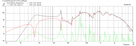
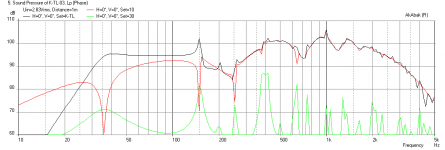
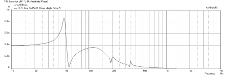
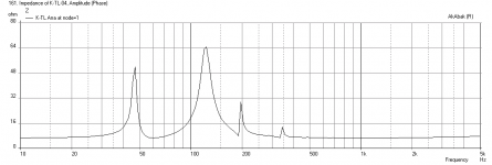
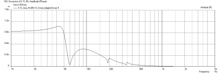
The AN Super8 works quite nicely in the full size 12 in K'nator. It has a high rising response that you may want to tame with some BSC or EQ'ing, otherwise it might be too bright or shouty.
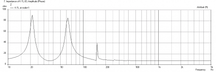
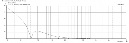
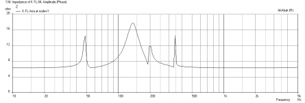
I also tried constricting the top channel to 0.5X and that really helped flatten the response out (second plot). Third plot is impedance, fourth is cone displacement. All for 0.5X choked case with 1 watt in at 1 m.
Attachments
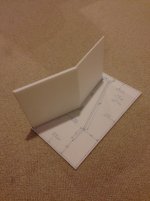
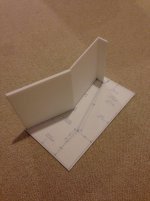
Build Log - No. 1 - Glue Internal Dividers & Baffle
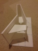
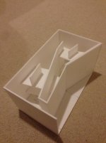
I started by drawing the plan on the side panel (which I have a typo on the plan). It is 15 & 3/8 in tall x 8 and 11/16 wide. Start by first gluing the two driver baffle panels together to double them up. Make sure they are offset so that they fit flush with the bottom wall. Then follow to the drawing and glue the top front panel, then top vent channel, the interior divider panel, then finally the bottom interior divider panel. Make sure you use a 90 deg piece of foam core to align the panels when they set in glue. These steps took me about 20 minutes. Easy.
I started by drawing the plan on the side panel (which I have a typo on the plan). It is 15 & 3/8 in tall x 8 and 11/16 wide. Start by first gluing the two driver baffle panels together to double them up. Make sure they are offset so that they fit flush with the bottom wall. Then follow to the drawing and glue the top front panel, then top vent channel, the interior divider panel, then finally the bottom interior divider panel. Make sure you use a 90 deg piece of foam core to align the panels when they set in glue. These steps took me about 20 minutes. Easy.
Attachments
Last edited:
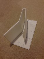
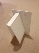
Build Log - No. 2 - Glue Exterior Walls and Bracing
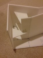
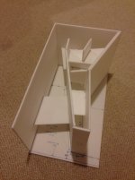
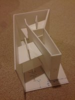
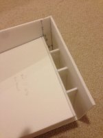
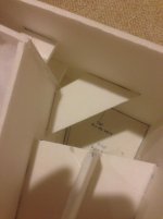
Next step is to glue the internal bracing inside the closed end section. Use scraps of foam core and hold it up to the section you want to brace and draw the outline of where the walls are, then cut the piece to fit perfectly. You can usually wedge it in place a little so that its own friction holds in place as the glue sets. Hot melt the brace and then wedge it in place. Add more hot glue fillets on the brace joint if you have enough room to get the gun in. The add the two braces for the lower diver panel to the front baffle, make sure it is wide enough not to interfere with driver placement. Add pieces of bracing to the side wall and attached to the driver chamber braces, one of them will be standing open for final capping of the side panel. Then glue the bottom wall on, after which add a brace between the lower vent divider and bottom. This will strengthen the bottom panel and keep it from acting like a drum head with the sound pressure. The glue the back wall on, you have to work fast as this is a long stretch to lay down hot glue before it hardens. Then add two pieces of bracing between the back wall and internal divider wall. Then glue the top cover on, after which add three small pieces of bracing between the top channel and top wall. Also add some bracing between the side wall and the back wall braces that were just installed. The top one will be left standing open to be glued when the final side capping operation takes place.
I also added a small brace between the top of the divider and the lid to reduce that large flat area from breathing with sound pressure. I think I have a total of 13 pieces of bracing. This series of steps takes about an hour due to the cutting and fitting all the braces.
Attachments
-
 Build-lower-brace-05.jpg159.1 KB · Views: 2,338
 -
 Build-bottom-brace-06.jpg145.1 KB · Views: 738
 -
 Build-upper-brace-07.jpg176.7 KB · Views: 728
 -
 Build-sidewall-brace-08.jpg167.1 KB · Views: 781
 -
 Build-top-panel-09.jpg149.6 KB · Views: 1,200
 -
 Build-top-vent-brace-11.jpg144.1 KB · Views: 792
 -
 Build-top-brace-16.jpg131.1 KB · Views: 669
Last edited:
0.75X Scale Karlsonator with TC9FD 3x3 Array
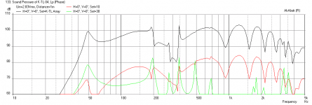
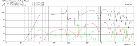
IG had the idea to stick 9 of the little Vifa's into this box (equivalent Sd of a 10 in driver). The advantage would be higher efficiency, very little cone movement so high power handling, and good HF response as the HF from a 3.5 in driver is much better than a 10 in driver. I had to tweak the design a little bit: the vent channel had to be enlarged by 2X (after applying 0.75X overall scale), and the rear chamber dimension and internal TL flowpath had to be enlarged by 1.2X in the channel depth dimension (length stays the same). So basically, the box will grow by 20% in depth. The front chamber and top vent length stays the same. So the results are actually very encouraging. The first plot is the freq response at 1 m, which shows an average SPL of about 95 dB which is consistent with running 3 parallel x 3 series drivers. The next plot is the impedance, which doesn't look too bad, nothing my amp can't handle, and the last plot shows how little cone movement there is as it is shared between 9 drivers. If someone (Melo Theory has 50 that I know of ) has a bunch of Vifa's lying around - this would be a fun experiment. I would make in plywood though as the sound pressure is quite high inside the box.
Certainly, a similar thing can be done with an array of the larger NS525's which are only $3.60 ea so you can get the equivalent of probably a 15 in driver. The cabinet would have to be scaled up by 1.2x probably... Should reach 30 Hz and be real loud.
IG had the idea to stick 9 of the little Vifa's into this box (equivalent Sd of a 10 in driver). The advantage would be higher efficiency, very little cone movement so high power handling, and good HF response as the HF from a 3.5 in driver is much better than a 10 in driver. I had to tweak the design a little bit: the vent channel had to be enlarged by 2X (after applying 0.75X overall scale), and the rear chamber dimension and internal TL flowpath had to be enlarged by 1.2X in the channel depth dimension (length stays the same). So basically, the box will grow by 20% in depth. The front chamber and top vent length stays the same. So the results are actually very encouraging. The first plot is the freq response at 1 m, which shows an average SPL of about 95 dB which is consistent with running 3 parallel x 3 series drivers. The next plot is the impedance, which doesn't look too bad, nothing my amp can't handle, and the last plot shows how little cone movement there is as it is shared between 9 drivers. If someone (Melo Theory has 50 that I know of
) has a bunch of Vifa's lying around - this would be a fun experiment. I would make in plywood though as the sound pressure is quite high inside the box. Certainly, a similar thing can be done with an array of the larger NS525's which are only $3.60 ea so you can get the equivalent of probably a 15 in driver. The cabinet would have to be scaled up by 1.2x probably... Should reach 30 Hz and be real loud.
Attachments
The broad valley and peak tell me there might be too much Vb for the combined drivers. Maybe we could get something flatter down to ~60Hz keeping the line length and making it more skinny on the other two dimensions. You don't have to re-do this unless you're curious, which is what brought me this idea to start with.
IG
IG
I was getting more bass by increasing Vb, which was why I added the 1.2X scaling on back TL and chamber chamber depth. I think the Vifa's have a very high Qts and need a lot of volume to work well. I have seen a formula for estimating Vb based on Qts and Sd or fs (GM has used it). I know that the BIB with a Vifa is a very voluminous box for how small the driver is. And with 9 of them, might be huge. The parallel driver idea may work better with a lower Qts driver - but then those aren't cheap. Maybe try with an FF85WK?
3X3 TB W3-315e Array
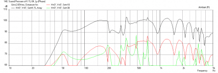
I tried putting a 3 in W3-315e driver with a Qts of about 0.5 and this seemed to do the trick. The response is much flatter now, I kept the overall scale at 0.75X and only scaled the vent up to 2.3X. This can definitely work but driver price is doubled.
I tried putting a 3 in W3-315e driver with a Qts of about 0.5 and this seemed to do the trick. The response is much flatter now, I kept the overall scale at 0.75X and only scaled the vent up to 2.3X. This can definitely work but driver price is doubled.
Attachments
Post #17 - AkAbak
Hi xrk971,
Thanks, the additional information looks good, on a quick read I think I can work from that. A lot of good ideas, I haven't yet tried to build math functions into AkAbak scripts to automatically recalculate the cross-sections and duct length from external cabinet dimension changes, but I'll try as soon as I find some "quiet time". This should be great for other boxes too, e.g.: MLTL, and TH.
Thanks again, Regards,
PS.: Nice build logs too.
- Home
- Loudspeakers
- Full Range
- Mini Karlsonator (0.53X) with Dual TC9FDs