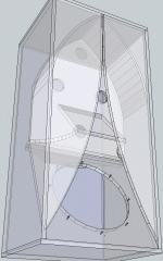
in a heretikal act, Karlson built at least one set of X15 with horns up front - probably for electronic organ - that one set had a very large vent so must have been the daddy of the Transylvania Power Co. product and other spinoffs
I should hack a large vent in my copies, extend its lower boundary with a shelf and see where it tunes and how it plays. (de-Q-ing )
I should hack a large vent in my copies, extend its lower boundary with a shelf and see where it tunes and how it plays. (de-Q-ing )
An externally hosted image should be here but it was not working when we last tested it.
Better horizontal dispersion over larger angles is another reason why the Karlson beats a bass reflex + direct radiator speaker. See analysis here: http://www.diyaudio.com/forums/full-range/213594-karlson-15.html#post3536693
I think Karlson spent alot of time messing with his upper chamber design and never
got complete satifaction. Dip was less with a shelf, but you had a harder time getting
upper chamber reflections out the slot. Tried with limted sucess to curve his upper
reflektor to focus horizontally at that horizontal gap in front of the shelf. Kept the
famous curve "Fig 6", even when he got rid of the shelf and all its advantages...
Where he blew it was to focus horizontally, when the exit slot is vertical. Needs a
pair of curved reflektors that crash the wavefronts together into a vertical stripe!
Then the midrange sound can get out, instead of bouncing around to no end...
---
Leverage every opportunity to lengthen the short circuit path that causes "the dip".
Leverage every opportunity to brace the wings and back. Make the bottom panel
removable so we don't have to look at them damn cheesy furniture bolts anymore.
I was first with those bolts on my wings. As-such, I feel free to opine on the trend.
Attachments
Last edited:
I don't think Karlson entirely blew it on the reflector - even a simple upper board at the top seems to affect image height or width when fed by a coaxial speaker. In the second installment of "Acoustic Transducers" (patent 3540544), Karlson showed a complex reflector made up of Fig.6 & Fig.8 - I suspect it would have been too expensive to implement.
what is the ideal shape for a K's front cavity? Kenpeter - what in your opinion can cause the first dip? 115BK with its large vent, etc. doesn't have much of a dip.
Fig.8 and Fig.6
https://www.google.com/patents/US35...ZDpJ7OB0AGjhIDAAg#v=onepage&q=3540544&f=false
what is the ideal shape for a K's front cavity? Kenpeter - what in your opinion can cause the first dip? 115BK with its large vent, etc. doesn't have much of a dip.
Fig.8 and Fig.6
https://www.google.com/patents/US35...ZDpJ7OB0AGjhIDAAg#v=onepage&q=3540544&f=false
Fig 8 makes little sense down low, there's no room on the sides for it.
Fig 8 makes little sense up high, the speaker doesn't reflect off the
wings like they were right in front of it... Probably work OK on an RJ.
Fig 6 is a messy fantasy that makes a horizontal parallel wavefront of
no particular focus, how it does anything useful besides smear the
reflections into submission, I don't know.
-----
Get the standing waves out before they bounce too many times.
By crashing every standing hotspot directly behind the exit slot.
We don't care where vertically on the slot, so long as all get out.
The first dip is the shortest path from back to front. Make sound
go around the side of the shelves, and taller coupler, and higher
internal vent (if placement doesn't ruin the chamber's reflective
properties) all give more distance. Distributed internal vents may
smear the dip, which can be useful too..
Last edited:
I think the first dip has more to do with the typical dip found in a higher order bandpass reflex box design. For example, a double bass reflex box tuned for 50 Hz will have a dip at about the same spot when the ports are not optimized or too aggressively tuned. So really, it is a function of the CSA of the inner shelf and the vent between the back and the front chamber. The front shelf will not affect this dip, nor the shape of the K aperture.
If we take the wings off and try to mount speaker on the front,
Then the shelf gets in the way of our tools, or you can't have a
shelf, or you might wanna drill an access hole through the shelf.
If we take off the back and try to mount the speaker behind the
baffle, then the same access problem occurs with the bottom
screws, and there is not really an easy drill for access solution
from the back.
If you just remove the bottom, then all the speaker mounting
points have plenty of room for tools directly behind them. Why
it takes 58 years to figure this out?
Last edited:
what do you think of GB's idea ? John Lapaire gave it a whirl in an 8 inch coupler - I have a rough version in a K6.5 but its rather flexy and the de-whizzered FE164 needs a helper tweeter when sitting near the floor
http://img141.imageshack.us/img141/124/karlsonator.png
http://img141.imageshack.us/img141/124/karlsonator.png
back to K15 - here's its ~groundplane response with the discontinued Eminence Beta 15cx coaxial (38 ounce magnet slug, advertised qts ~0.58) vs a JBL M151 instrument speaker. I made the lowpass gap tight for the weak motor coax to get it to sound reasonably taut on Mickey Hart's "DAFOS" on drum beats and when the "Beast" was dropped - for a mushmotor coax, it didn't sound too shabby. I should had played with the vent area to see if it would do similar but only had so much time and no help to move stuff.
Thiele-Small Parameters
Resonant Frequency (fs) 34 Hz
Impedance (Re) 5.54 ohms
Coil Inductance (Le) 1.06mH
Electromagnetic Q (Qes) .58
Mechanical Q (Qms) 7.68
Total Q (Qts) .54
Compliance Equivalent Vol. (Vas) 366.4 Liters/12.94cu. ft.
Voice Coil Overhang (Xmax) 3.0mm
Surface area of Cone (Sd) .08237m2
An externally hosted image should be here but it was not working when we last tested it.
Last edited:
I think the first dip has more to do with the typical dip found in a higher order bandpass reflex box design. For example, a double bass reflex box tuned for 50 Hz will have a dip at about the same spot when the ports are not optimized or too aggressively tuned. So really, it is a function of the CSA of the inner shelf and the vent between the back and the front chamber. The front shelf will not affect this dip, nor the shape of the K aperture.
Maybe, but I like my own theory better than anything reality has to offer.
There's many things going on simultaneously, and your suggestion is one
of them, but I think "the dip" of a K misbehaves much as a tapped horn.
The shelf is good for doing three things:
Lengthen the short circuit path. Depending the location of the
internal vent, this might be trivial. It isn't trivial on the K15...
Provide a direct bounce out for much of the midrange.
Split the path of midrange to the upper chamber, so interference
patterns will make a vertical stripe, directly behind the exit slot.
what do you think of GB's idea ? John Lapaire gave it a whirl in an 8 inch coupler - I have a rough version in a K6.5 but its rather flexy and the de-whizzered FE164 needs a helper tweeter when sitting near the floor
http://img141.imageshack.us/img141/124/karlsonator.png
I think the xtra stub would be helfpul.
IG81 suggests an RJ with such a stub: http://www.diyaudio.com/forums/full-range/213594-karlson-11.html#post3529219
I suggest a K18 with stubs, one post below that...
Last edited:
I have an 8 cubic foot bulk diy K-coupler with a 3-panel "cupped" reflector - no rear shelf in the groundplane graph below - two 4.5" holes for its vent so it could be tuned lower with 4" pvc and also mount an internal K tube
here's the effect at groundplane of a 5" deep front shelf - tuned just by the 4.5" holes
here's the effect at groundplane of a 5" deep front shelf - tuned just by the 4.5" holes
An externally hosted image should be here but it was not working when we last tested it.
Last edited:
I was thinking about how the short-circuit path might be best kept short in certain instances. When I tried adding a partition to the back of my SK8 to give a bit of extra length to the vent and basically turn the back chamber into a short tapering line, it only made things worse with choppier midrange.
I also think that the Karlson's tapped-horn operation can be fairly dominant when using large vents located higher in the enclosure.
IG
I also think that the Karlson's tapped-horn operation can be fairly dominant when using large vents located higher in the enclosure.
IG
Below is what I described in the previous post and the effect on the response. As mentionned in the graph's legend, the vertical division was actually 3.5", so not quite as long as visually represented on the drawing.
This has me wonder about vent proximity to the driver and length thereof, in order to get as much smooth gain bandwidth as possible. The SK8 already has over 2 octaves and reaching for 3 octaves might just be doable, but no more IMO. I've always wanted to see what a bit of slot-loading to constrict the driver's front would do in a Karlson. Taking these two ideas together would basically be an R-J venting scheme within a Karlson.
IG
An externally hosted image should be here but it was not working when we last tested it.
An externally hosted image should be here but it was not working when we last tested it.
This has me wonder about vent proximity to the driver and length thereof, in order to get as much smooth gain bandwidth as possible. The SK8 already has over 2 octaves and reaching for 3 octaves might just be doable, but no more IMO. I've always wanted to see what a bit of slot-loading to constrict the driver's front would do in a Karlson. Taking these two ideas together would basically be an R-J venting scheme within a Karlson.
IG
Last edited:
FYI, this is a 6th order BP and since the tap fills in the ~264 Hz 3rd harmonic dip, it's already ideally tuned.........
GM
Most anything I've tried to change with the SK8 design has yet to be better than the original formula, so I came to believe that it's ideally tuned as well.
You often mention how Karlsons are most often Nth order BP systems and I can't say I disagree. The back-chamber itself is usually a simple reflex or quasi-DBR at times, but how do you view the front chamber's action? The typically smaller Vb and large K-slot area make no sense for a Helmholtz tuning anywhere close to what we deal with; ~115Hz for K15, ~155Hz for K12 and ~200Hz for the above little SK8. I've usually found correlation between vertical height and the front tuning (second impedance minima on a Z plot, between 2nd and tiny 3rd peaks, if I interpret this correctly). This tuning is often a quarter-wave for ~90-95% of the internal height.
When simulating a 6th order BP in WinISD, I set this frequency as the front tuning without regards for the in-software Helmholtz vent dimensions and set Ql=3 for this Vb, which gets me a close enough match to actual measurements.
IG
So when the front shelf is added does it become an 8th order bandpass? I seem to recall hearing on one of these threads that the K15 was 8th order.
I am thinking of taking step back and designing a Karlson type enclosure from the standpoint of a multiple-resonator bandpass with Karlson aperture output coupler. I am not sure if having the driver right behind the large part of the aperture really is impacting that much with the "tapped horn" behavior. I don't really think there is much tapped horn action going here. This may free up the spatial design constraints and open up the design space to allow this to be optimized for almost any size driver. Right now, moving away from the K15 cabinet by any more than 12/15 ratio ruins it. Too much geometry dependence coupled to chamber volumes. They need to be separated - thinkseparate chambers connected by interchangeable round ducts. Final chamber has K-slot and first chamber has driver.
I am thinking of taking step back and designing a Karlson type enclosure from the standpoint of a multiple-resonator bandpass with Karlson aperture output coupler. I am not sure if having the driver right behind the large part of the aperture really is impacting that much with the "tapped horn" behavior. I don't really think there is much tapped horn action going here. This may free up the spatial design constraints and open up the design space to allow this to be optimized for almost any size driver. Right now, moving away from the K15 cabinet by any more than 12/15 ratio ruins it. Too much geometry dependence coupled to chamber volumes. They need to be separated - thinkseparate chambers connected by interchangeable round ducts. Final chamber has K-slot and first chamber has driver.
All implementations of a front shelf I've seen were nowhere long enough to add additional poles. It'd have to be full cabinet width and touch the wings for this to happen IMO, even then?
I think the K-slot will trap some air on long enough a path for a top-vent Karlson to have some tapped-horn action. There will be some de-Q'in action as well because of it and other effects can then start to dominate, wether neckless-Helmholtz or QW or whathaveya.") A vent anywhere lower than the very top of the coupler, including distributed schemes, will probably allow for very little TH action to go on.
A vent anywhere lower than the very top of the coupler, including distributed schemes, will probably allow for very little TH action to go on.
IG
I think the K-slot will trap some air on long enough a path for a top-vent Karlson to have some tapped-horn action. There will be some de-Q'in action as well because of it and other effects can then start to dominate, wether neckless-Helmholtz or QW or whathaveya.
A vent anywhere lower than the very top of the coupler, including distributed schemes, will probably allow for very little TH action to go on.IG
- Home
- Loudspeakers
- Full Range
- A Speaker that Kicks Butt in Large Spaces