Hello,
for DIY'ers who would like to build a "dipol 08" style
speaker for private use, i decided to post some raw
sketches (of the baffle dimensions at least) and a list of
crossover parts as a start.
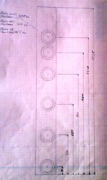
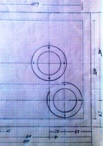
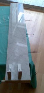
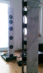
The baffle should be executed with conical driver cutouts
on the rear and be as rigid but thin and highly damped as
possible. I used a composite with a constraint layer
damper inbetween.
Many variants are possible including "omitted backbone"
for less effort or "reduced size lady edition" ...
Nevertheless, the backbone damper including magnet
mounting of the drivers improves the quality of bass to
midrange reproduction a lot and makes up a good part of
the fascination coming with this speaker.
The backbone is mouted flexibly and damped to the foot
and has a resonance as a "standing pendulum" of approx.
5Hz in my version, when the foot is "clamped" to the
bottom (which is not done usually during operation).
A little shrinking in height, maybe 10%, please do diffraction
simulations first and compare to the original, might be
advantageous for people sitting low and listening close.
If sparkle is missing when listening close and sitting low,
a little tilting forward of the speaker (nearly invisibly) is
also a practical solution (loss in sparkle is only little when
listening "close low"). Listening distances from 1.5m
on upward are recommended. I testet up to 7m listening
distances with very good results in homogeneity and
consistency in the whole listenening room.
I post the files "as they are". Please be understanding,
that i cannot do any consultancy in depth for single
projects and possible variants, as i am occupied with
different projects currently. But i will try to answer
common questions - if any - from time to time.
Remark: A dedicated dipole subwoofer is strongly recommended.
Dipol 08 is easiest crossesd in using a 1. order passive line level filter
("PLLXO") at 80Hz. Fullrange operation is possible, but dynamic headroom
is less. Without subwoofer only some chamber music and few jazz recordings
are enjoyful to my taste ...
---
Since the driver positions are badly readable on the picture
of the handsketch, please refer to the attached text files.
Kind Regards
for DIY'ers who would like to build a "dipol 08" style
speaker for private use, i decided to post some raw
sketches (of the baffle dimensions at least) and a list of
crossover parts as a start.
The baffle should be executed with conical driver cutouts
on the rear and be as rigid but thin and highly damped as
possible. I used a composite with a constraint layer
damper inbetween.
Many variants are possible including "omitted backbone"
for less effort or "reduced size lady edition" ...
Nevertheless, the backbone damper including magnet
mounting of the drivers improves the quality of bass to
midrange reproduction a lot and makes up a good part of
the fascination coming with this speaker.
The backbone is mouted flexibly and damped to the foot
and has a resonance as a "standing pendulum" of approx.
5Hz in my version, when the foot is "clamped" to the
bottom (which is not done usually during operation).
A little shrinking in height, maybe 10%, please do diffraction
simulations first and compare to the original, might be
advantageous for people sitting low and listening close.
If sparkle is missing when listening close and sitting low,
a little tilting forward of the speaker (nearly invisibly) is
also a practical solution (loss in sparkle is only little when
listening "close low"). Listening distances from 1.5m
on upward are recommended. I testet up to 7m listening
distances with very good results in homogeneity and
consistency in the whole listenening room.
I post the files "as they are". Please be understanding,
that i cannot do any consultancy in depth for single
projects and possible variants, as i am occupied with
different projects currently. But i will try to answer
common questions - if any - from time to time.
Remark: A dedicated dipole subwoofer is strongly recommended.
Dipol 08 is easiest crossesd in using a 1. order passive line level filter
("PLLXO") at 80Hz. Fullrange operation is possible, but dynamic headroom
is less. Without subwoofer only some chamber music and few jazz recordings
are enjoyful to my taste ...
---
Since the driver positions are badly readable on the picture
of the handsketch, please refer to the attached text files.
Kind Regards
Attachments
-
 Dipol08_DriverPositions.jpg148.9 KB · Views: 1,021
 -
 Dipol08_Main_XO.jpg162.1 KB · Views: 988
 -
 Dipol08_SketchTweeterPanel_01.jpg145.3 KB · Views: 958
 -
 Dipol08_SketchTweeterPanel_02.jpg168 KB · Views: 952
 -
 Dipol08_SketchTweeterPanel_03.jpg207.8 KB · Views: 930
 -
Dipol08_TweeterProperties.txt1.8 KB · Views: 176
-
Dipol08_CrossoverPartsAndBaffleSize.txt1.5 KB · Views: 192
-
 Dipol08_TweeterPanel_XO.jpg145.6 KB · Views: 204
Last edited:
I used 2 sheets of High Pressure Laminate
(6mm thickness each) with about > 2mm dampening glue
inbetween.
Rear sheet with larger driver cutout .... to make it more
"open" to the rear.
That is not an optimum material, but since the excitation
is very low - achieved by the magnet mounting - it is
OK. Without backbone it would also be too floppy due
to it's height ...
I would try something different in the next one ...
Best
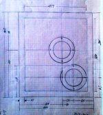
For those who like to play around using EDGE, here
are 2 files representing the approximate configuration
of "dipol 08" as a starting point.
The file with suffix "HT" includes only the 3 upper
drivers and no mirrored baffle. The other file includes
all 6 drivers and a mirrored baffle, representing the
bottom reflections from the array.
The baffle is rotated by 90 degrees in the sketch,
so the bottom line has to be imagined vertically
in the middle of the sketch, separating the double
height baffle (baffle and bottom mirrored image)
into 2 halves.
This way the image fits better into EDGE's sketch
window ... you cannot handle a tall baffle
including bottom reflections otherwise.
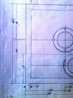
If you make changes, be shure to change the
mirrored baffle accordingly - mirorring is done
manually, it is not an EDGE built in feature ...
File "HT" has better approximation above 2-4Khz,
since the lower drivers are rolled off and floor
reflections are less pronounced.
The third file (without the "mod2" suffix) allows
comparison with an array having equidistant
driver placement.
---
EDGE from Tolvan data:
Home of the Edge
Of course you can also use other diffraction simulators
of your choice. Think of the results as being "tendencies",
not representing what we call "reality".
are 2 files representing the approximate configuration
of "dipol 08" as a starting point.
The file with suffix "HT" includes only the 3 upper
drivers and no mirrored baffle. The other file includes
all 6 drivers and a mirrored baffle, representing the
bottom reflections from the array.
The baffle is rotated by 90 degrees in the sketch,
so the bottom line has to be imagined vertically
in the middle of the sketch, separating the double
height baffle (baffle and bottom mirrored image)
into 2 halves.
This way the image fits better into EDGE's sketch
window ... you cannot handle a tall baffle
including bottom reflections otherwise.
If you make changes, be shure to change the
mirrored baffle accordingly - mirorring is done
manually, it is not an EDGE built in feature ...
File "HT" has better approximation above 2-4Khz,
since the lower drivers are rolled off and floor
reflections are less pronounced.
The third file (without the "mod2" suffix) allows
comparison with an array having equidistant
driver placement.
---
EDGE from Tolvan data:
Home of the Edge
Of course you can also use other diffraction simulators
of your choice. Think of the results as being "tendencies",
not representing what we call "reality".
Attachments
Baffle Theory
Here's a theory question for you Oliver. If the drivers were totally supported from the magnet, the baffle could then be built to only consider (1) seperating the rear wave from the front wave, and (2) help encourage desired dispersion characteristics.
In theory the baffle could then be made of an anti-resonant material such as closed cell foam, gypsum or even thin foamboard, since 100% of the support duties would now be releaved. The drivers would not have to physically attach to the baffle, only be placed close enough to simulate a seal.
To me this sounds like an interesting approach to reducing baffle and driver noise, and reduce the speaker's overall weight. Additionally, a "foam" baffle could be shaped to facilitate imgaing and dispersion.
Do you see a downside to this?
Ed, i am with you in most points.
But please do not forget the excitation of the baffle
due to sound pressure, having opposite sign on front
and rear ....
Dipole 08 has kind of purely magnet mounted drivers,
if you knock against the driver baskets from the front,
excitation of the front baffle is close to nothing.
A rather soft, highly damped but dense baffle material
like some rubber granulate e.g. is surely interesting,
but even for pure magnet mounting
("baffle gasket only") you will need at least some
stiffness to withstand deformation due to sound pressure
at low frequencies ....
And we still need that stiffness without the baffle being
extraordinarily thick.
Lead ... is contaminative unfortunately.
Best
Last edited:
Thank you darkmoebius,
and here comes the first correction:
1) The 1st picture (Baffle Sketch) shows the LEFT speaker.
The text said otherwise ... sorry, uploaded a new version.
FR is more balanced - as in almost all OBs - when
the shortest path between drivers an baffle edge points
inwards while listening.
The tweeters are placed accordingly:
Shorter path to the edge inward pointing while listening.
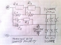
2) Remark: Since there is only one of the tweeters
playing to the top frequencies, its position would
normally be chosen closer to the uppermost fullranger.
I decided to do different, as the more asymmetric
position of the lower tweeter is likely to produce
more unwanted reflections with the backbone.
So it is the upper tweeter, reproducing the
highest frequencies, which can radiate more freely
with the given backbone confguration.
Cheers
and here comes the first correction:
1) The 1st picture (Baffle Sketch) shows the LEFT speaker.
The text said otherwise ... sorry, uploaded a new version.
FR is more balanced - as in almost all OBs - when
the shortest path between drivers an baffle edge points
inwards while listening.
The tweeters are placed accordingly:
Shorter path to the edge inward pointing while listening.
2) Remark: Since there is only one of the tweeters
playing to the top frequencies, its position would
normally be chosen closer to the uppermost fullranger.
I decided to do different, as the more asymmetric
position of the lower tweeter is likely to produce
more unwanted reflections with the backbone.
So it is the upper tweeter, reproducing the
highest frequencies, which can radiate more freely
with the given backbone confguration.
Cheers
Attachments
Last edited:
If you build this line array, it will contribute to
best performance if you select your drivers for
symmetry of the left and the right array.
I leave it up to you, whether to rely on measurement
of the drivers solely or prefer an "auditive matching",
which is also possible.
You will notice with most drivers, than none of the
12 will sound the same.
For the upper trio of drivers, which reproduces the
highs predominantly, the candidates which produce
somewhat more "sparkle" but sound balanced and
"unobtrusive" should be selected.
In short: Divide your drivers in a lesser and a better
half due to "presence and sparkle" region and use the
better ones to play in the upper trio.
Some examples for matching the six best for the highs:
- A driver sounding somewhat "beasty" due to being
a little hot (in relation to the others) around 7Khz e.g.
should not play at an elevated position: Best for this
driver is 3rd from above.
- A driver which is unobtrusive but a little more dull
than the others is placed 1st. from above.
- The driver seeming to be the most balanced
one is placed 2nd from above.
For every driver, similar partners should play on the
corresponding positions in the left and right speakers.
---
- Do those selections after a sufficient period of
burning in.
- Have also a look at resonance frequencies and
Rg.
For the 3 lower drivers those are the main
"distinguishing marks" to balance left and right
speaker. The lower the driver's mounting positions
are in the array, the closer the resonances between
left and right "partners" should match.
All in all this is not an "esoterical" approach !
That "balancing and selecting" causes a little effort
but contributes significantly to a simple crossover,
since there is less compensation needed, the speaker
sounds more unobtrusive and balanced because you
simply make the best of the material purchased.
Send drivers with strong deviations back to the dealer !
Same for drivers which have increased noise level !
If the customer does not send back strongly deviating
drivers, the dealers and the manufacturer will not feel
sufficient pain to improve quality. You are in fact helping
them ...
Many manufacturers are pretty good nowadays, but the
CSS FR 125 S were not very homogenous due to
tolerances and quality , as i purchased them in Germany
about 2 years ago.
I hope this has changed by now, since the drivers are
very good by design.
---
Of course fullrangers should always be matched pairs,
no matter which manufacturer.
And as a personal remark:
I seriously wonder why this issue is not being
discussed in here with same enthusiasm like e.g.
"enabling" ... since serial tolerances and quality is
undoubtedly an issue affecting speaker pair symmetry
and speaker quality.
Best Oliver
Last edited:
And as a personal remark:
I seriously wonder why this issue is not being
discussed in here with same enthusiasm like e.g.
"enabling" ... since serial tolerances and quality is
undoubtedly an issue affecting speaker pair symmetry
and speaker quality.
Best Oliver
My thought is that rooms are rarely matched left/right - quite the opposite, and that influences performance more than matching components
Regards /Bo
I do not accept that argument, although you are right
concerning the modal range of the room below
Schröder frequency.
If e.g. a left speaker sounds somewhat "nasal"
due to tolerances compared to the right one, you can
distinguish both when playing from a position nearby
each other. Using white noise e.g. , even auditive
distinction is easy.
But you can also distinguish the speakers when standing
at different positions, distance and angle pointing at the
listener should be the same.
Audibility surely depends on the amount of deviation.
But quality is about controlling deviation, not a about
ignoring it. Sad but true ... all the factors contributing
to further deviation (room ..) can go into compensative
direction but can also worsen the deviation.
A deviation in the direct sound will mostly be audible
above Schröder Frequency and be more audible as
higher you go in frequency towards the presence range.
Using your argumentation, we could even listen with
speakers of different type on the left and the right position
in a stereo setup.
It is a typical "doesn't matter anyhow" argument ...
As a further point a dipole line array is by far more directional than
e.g. a monopole source ... room contribution is much reduced
compared to conventional speakers, which possibly increases the
need for looking at symmetry.
Best
Last edited:
It is a typical "doesn't matter anyhow" argument ...
Best
It is a to-each-his-own-argument. If u wanna match ur own batch of resistors, go ahead. I aint doing it
Regards /Bo
Danerius,
i am giving practical hints here, how to get the best
result when building this particular speaker.
Since i have developed and built it, i should have some
practical experience which i share with other members.
I did not say anything about measuring and matching
the resistors or other crossover components ...
i was talking about the drivers.
And i was talking about a particular driver, which
seemed to have had non optimum consistency in
serial production in the past.
My hints are about handling that - and possibly turning
deviations of the drivers into an advantage ... although
it will also apply to other drivers used in a comparable
configuration.
Building a speaker is not only "building accordingly
to plan", there are also details in execution which
contribute to the quality which can be achieved.
And as there are measures, which i have found to
influence quality and do not even increase cost,
i should mention them to those who are interested.
Kind Regards
Since drivers with lower fs will also have lower
efficiency, the bottom position is best for the
lowest fs drivers ... since the bottom position
has the longest effective dipole path length.
If you have a set of slightly varying drivers, there
will be truly a place for everyone ... but this kind
of selection is by far not as important as selection
due to mid to high frequency response.
Last edited:
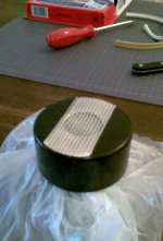
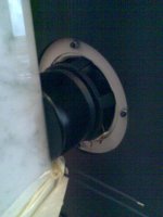
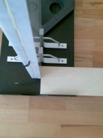
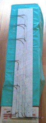
Some pics from mounting, here glueing the drivers
to the stone spine ...
to the stone spine ...
Attachments
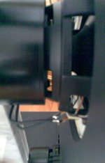
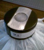
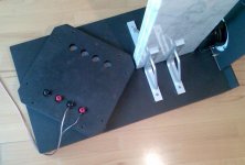
Wiring of the drivers could be simplified now,
but as the crossover design was not settled
is was easier to have the to connectors of upper
and lower drivers group accessible separately
in the croccover ...
...
Mounting of stand and spine ...
but as the crossover design was not settled
is was easier to have the to connectors of upper
and lower drivers group accessible separately
in the croccover ...
...
Mounting of stand and spine ...
Attachments
Last edited:
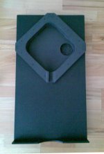
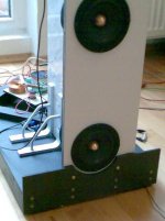
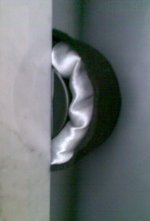
Left speaker being built,
optional rear muffler,
first crossover tests,
crossover cover closed with
1st version of crossover builtin ...
optional rear muffler,
first crossover tests,
crossover cover closed with
1st version of crossover builtin ...
Attachments
Last edited:
Thanks for sharing. All fittings and overall assembly are cleverly and tidily done! How nice I love that wiring method.
-------------
I'm very interested in various line arrays. Some design ideas keep popping in my mind. Besides all the dilemmas and difficulties in designing which have been thoroughly discussed, I'd like to raise another question, about multi-driver.
I have a feeling, when the system is playing quietly and the level gets lower than a point, some details would be gone.
Other than being submerged by the background noises, hearing's sensitivity drop at both ends of spectrum, and possible intrinsic non-linearity of (my) hearing or even the air itself, would it be possible that the speaker driver(s) also hit the non-linear operation zone of the low level side?
I mean, when playing very very quiet, the amplitude is lower than a point, the rise and fall of the signal produced by the voice-coil-cone-assembly might largely fail to track the input because of all kinds of non-linearity in the electrical and mechanical constructions.
For example, maybe small, but there should be a [static friction] in the suspensions of the driver (as physics told us). When the force (by the VC) gets larger than that, then it starts moving. If the force is very small, to a threshold, it might fail to move the cone.
And, there is inevitably some flexibility in voice coil itself and the bonding between VC and cone (not to mention the floppy cone). After all, nothing is perfectly rigid. So, some of the force must be eaten here.
Sorry for the hair-splitting, but I think those are not just (my own) imaginations.
So, I got an impression that smaller, lighter drivers usually behave better at such condition. (or maybe it's the same thing as the term "downward dynamics" brought by Planet10?) OTOH, my 18" woofers are the typical bad example. They are good at playing loud, not quiet.
In a line array, there're many drivers. When playing quiet, each driver is moving even less than the single driver in ordinary speakers. So I'd guess it would hit the "low level threshold" earlier. (such phenomenon might also be non-linear, though...)
So, how does the line array behave in reality when playing very quiet? Would you please share?
I love that wiring method.-------------
I'm very interested in various line arrays. Some design ideas keep popping in my mind. Besides all the dilemmas and difficulties in designing which have been thoroughly discussed, I'd like to raise another question, about multi-driver.
I have a feeling, when the system is playing quietly and the level gets lower than a point, some details would be gone.
Other than being submerged by the background noises, hearing's sensitivity drop at both ends of spectrum, and possible intrinsic non-linearity of (my) hearing or even the air itself, would it be possible that the speaker driver(s) also hit the non-linear operation zone of the low level side?
I mean, when playing very very quiet, the amplitude is lower than a point, the rise and fall of the signal produced by the voice-coil-cone-assembly might largely fail to track the input because of all kinds of non-linearity in the electrical and mechanical constructions.
For example, maybe small, but there should be a [static friction] in the suspensions of the driver (as physics told us). When the force (by the VC) gets larger than that, then it starts moving. If the force is very small, to a threshold, it might fail to move the cone.
And, there is inevitably some flexibility in voice coil itself and the bonding between VC and cone (not to mention the floppy cone). After all, nothing is perfectly rigid. So, some of the force must be eaten here.
Sorry for the hair-splitting, but I think those are not just (my own) imaginations.
So, I got an impression that smaller, lighter drivers usually behave better at such condition. (or maybe it's the same thing as the term "downward dynamics" brought by Planet10?) OTOH, my 18" woofers are the typical bad example. They are good at playing loud, not quiet.
In a line array, there're many drivers. When playing quiet, each driver is moving even less than the single driver in ordinary speakers. So I'd guess it would hit the "low level threshold" earlier. (such phenomenon might also be non-linear, though...)
So, how does the line array behave in reality when playing very quiet? Would you please share?
...
I mean, when playing very very quiet, the amplitude is lower than a point, the rise and fall of the signal produced by the voice-coil-cone-assembly might largely fail to track the input because of all kinds of non-linearity in the electrical and mechanical constructions.
For example, maybe small, but there should be a [static friction] in the suspensions of the driver (as physics told us). When the force (by the VC) gets larger than that, then it starts moving. If the force is very small, to a threshold, it might fail to move the cone.
...
Hello CLS,
nice to meet you here ...
i observed something - which may point into that
direction - when i was tuning the rear tweeter panel.
I decided for that tweeter panel, because asymmetry
in dispersion of upper presence and brillance region
led to inconsistencies.
When tuning the speaker to have sufficient "sparkle"
to be experienced at all "useful" listening positions it
turned out that it sounded unecessarily sharp or
"beasty" with some music.
The drawback of rear radiation dropping in the highs,
could not be compensated with the front radition.
That was why i made the rear tweeter panel, but
since i did not want it to spoil homogeneity i listened
very carefully while tuning the tweeter panel's
crossover and i also listened at very low levels ...
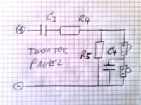
In that situation the tweeters could also be driven
"fullrange" (mind the L-Pad), so i omitted the
capacitor "C3" for a while.
I experienced, that the subtle effect of the tweeter panel
was improved at low levels, giving slightly more detail
at very quit music passages.
The effect was so subtle, that i normally would not
make a big story of it, but my personal impression
was stable - even though i know that it might be
close to "subliminal".
I suspected the capacitor to cause the loss in detail ...
and tried different types also making it so large that
a change in frequency response caused by presence
of C3 could be excluded.
What i believe finally is, that it was not the
capacitor causing the subtle change, but the low
frequency components causing motion of the tweeters
even at low levels - thereby possibly mitigating those
effects you mention above.
If you observe a cat before jumping, it will not stay
motionless before the jump but preparing to it by
slightly "rocking" herself ... i like to take this as an
analogy.
There must be friction, which causes relatively increased
nonlinearities around the rest position of a vibrational
system. And i think distortion measurements point
towards increased distorsion at very low levels too.
---
In the end i decided to include C3 in a very large and
high quality version as a compromise, for reasons of
durability of the speaker ... most of my speakers will
be used by other persons and not by myself, so
durability and robustness is always a priority.
But i sometimes thought about some part of the
"analog/vinyl magic" experienced by some
audiophiles comes from subsonic vibration
of the speakers, causing a fullranger or a woofer to
oscillate permanently around its rest position, thereby
possibly increasing detail by partly overcoming the
nonlinearities at low excursions.
Maybe some subsonics also causing psychoacoustical
effects ... but that is another story.
---
If so, i could propose a - level adaptive - "rumble"
simulator here, which causes inaudible excursion
of the drivers (and amps!), to increase performance
at low levels.
Compared to all the high end "snake oil" sold, this
could indeed be a real improvement to some systems.
---
In fact is does not solve the problems for the tweeters
in a multiway. A tweeter with impregnated surround,
being the suspension at the same time might suffer
more from that than a fullranger, also excursions are
very small at low levels.
--------
But to answer your initial question, the fullrangers
themselves do not show obvious effects at lower
levels and the whole speaker plays rather "level
consistent" to my ears.
The 80Hz 1st order PLLXO highpass helps increasing
the dynamic headroom and makes the system playing
more "relaxed" at higher levels. That is a major point
concerning dynamics. In that configuration the system
can go very loud - absolutely sufficient for the majority
of listeners in a living room i would say.
Kind Regards
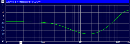
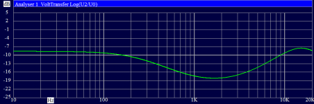
These two diagrams show a simulation of the voltage
transfer for the upper and the lower trio of drivers
respectively, to illustrate the concept of the equalizer/crossover.
Loads are assumed as 2.33 Ohms (3 drivers in parallel) and
130 micro Henry VC inductance in series, to represent each group
of drivers.
The real object differs slightly.
The falling slope compensates the rising efficiency
of the OB and also vertical directivity, whereas the
lift in the highs is mainly due to falling energy
response of the fullrangers and the upper trio
getting more dominant in the highs (power tapering).
The frequency dependent voltage shift between the
driver groups is very smooth, so you cannot really
detect which fullranger reproduces which frequency
range from usual listening positions, the array sounds
as being centered subjectively around the 2nd driver
from above as a consequence of the combined effects
of distance weighting and power tapering.
---
For those who already used an FR 125 S, this is a
configuration which makes the driver sound sufficiently
present and gives real sparkle, but is in no way overbright.
As the directivity is less varying than with a single driver
in a monopole box, the insufficient energy radiated in the
highs gets very obvious here and must be compensated for.
Left: Upper driver group
Right: Lower driver group
Attachments
Last edited:
- Status
- This old topic is closed. If you want to reopen this topic, contact a moderator using the "Report Post" button.
- Home
- Loudspeakers
- Full Range
- "Dipol 08" Baffle Dimension and List of Crossover Parts