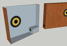
Here's a design I'm considering for use in a Uni bedroom. The concept is a Monacor SPH-30X in a ~2L ported enclosure. This doesn't give massive bass extension, but I have heard this confguration and it gives a suprisingly good rendering of most bass lines.
As these speakers will be on a desktop, it's nearly unavoidable they will be near a wall (in my case they will have to be right next to it) Hence, the enclosure is made very flat so as to gain baffle reflections from the whole wall, a bit like if the speaker were mounted in-wall (in theory). It should not require baffle step correction. The ports are mounted on the thin edges at the bottom, placing them very near to the wall, with the intention of gaining boundary reinforcement from the wall as well as the desk.
(image shows effect of baffle if compensated electrically. the driver is located to reduce frequency anomalies and make them complimentary to the driver's natural response where possible.)
The Monacor driver is very shallow as it uses a small neodynium motor. It is rather efficient and works in a small box volume, essential for such a flat design. It has a nasty looking peak at 10KHz, but this generally sounds ok slightly off axis. I'd probably build the front, back, top and bottom from 9mm plywood, but heavily braced. The edges would likely be made from timber planks, 12-18mm thick. The sloped enclosure both angles the driver toward the listener and reduces parallel internal walls.
I'd probably apply a roundover along the left and right edges, but it's hard to show on Sketchup.
I have concerns with this design (aside from the, imo, unappealing aesthetic!). The driver rear side is placed very near the back wall, how concerned should one be about reflections back through the light cone? What are good measures to avoid smearing the sound; acoustic foam behind the driver? The Edge gives a 'F2' frequency at 441Hz, is the enclosure thin enough to take advantage of the wall reinforcement with this in mind? I would assume so myself, the wavelength at this frequency is 780mm and the enclosure thickness is just 74mm at most, but this isn't something I'm experienced with. Would there be more leakage into a room behind these due to thier close proximity to the wall, or does it make no difference? They don't exactly pound out bass so I'm guessing not.
Any input appreciated!
An externally hosted image should be here but it was not working when we last tested it.
As these speakers will be on a desktop, it's nearly unavoidable they will be near a wall (in my case they will have to be right next to it) Hence, the enclosure is made very flat so as to gain baffle reflections from the whole wall, a bit like if the speaker were mounted in-wall (in theory). It should not require baffle step correction. The ports are mounted on the thin edges at the bottom, placing them very near to the wall, with the intention of gaining boundary reinforcement from the wall as well as the desk.
An externally hosted image should be here but it was not working when we last tested it.
(image shows effect of baffle if compensated electrically. the driver is located to reduce frequency anomalies and make them complimentary to the driver's natural response where possible.)
The Monacor driver is very shallow as it uses a small neodynium motor. It is rather efficient and works in a small box volume, essential for such a flat design. It has a nasty looking peak at 10KHz, but this generally sounds ok slightly off axis. I'd probably build the front, back, top and bottom from 9mm plywood, but heavily braced. The edges would likely be made from timber planks, 12-18mm thick. The sloped enclosure both angles the driver toward the listener and reduces parallel internal walls.
An externally hosted image should be here but it was not working when we last tested it.
An externally hosted image should be here but it was not working when we last tested it.
I'd probably apply a roundover along the left and right edges, but it's hard to show on Sketchup.
I have concerns with this design (aside from the, imo, unappealing aesthetic!). The driver rear side is placed very near the back wall, how concerned should one be about reflections back through the light cone? What are good measures to avoid smearing the sound; acoustic foam behind the driver? The Edge gives a 'F2' frequency at 441Hz, is the enclosure thin enough to take advantage of the wall reinforcement with this in mind? I would assume so myself, the wavelength at this frequency is 780mm and the enclosure thickness is just 74mm at most, but this isn't something I'm experienced with. Would there be more leakage into a room behind these due to thier close proximity to the wall, or does it make no difference? They don't exactly pound out bass so I'm guessing not.
Any input appreciated!
A good point! I only have a photo of the desk to work from, but there are some CDs on it, which will be 120cm. I'd say there's enough room for the pair and my 17" non-widescreen monitor. For a lot of people that could be an issue, but in this case I have a rather broad desk and narrow monitor. At worst, the bass-port end would sit just slightly behind the monitor, which shouldn't be an issue.
Any other input on this design? I actually have one 4ohm SPH-30X driver, so could try it out if it is likely to be successful?
Any other input on this design? I actually have one 4ohm SPH-30X driver, so could try it out if it is likely to be successful?
FWIW, making the baffle proper just big enough to mount the driver and feathering (slanting) the top and sides of the baffle is both aesthetically and acoustically superior if you have the room and IME using slit vent terminations on one or both of the sides is superior overall to 1 pi loading unless the response is rolled off down low.
I've yet to try it on desktop speakers, but the MLTLs I've done for tiny room/whatever apps have all been crowd pleasers.
GM
I've yet to try it on desktop speakers, but the MLTLs I've done for tiny room/whatever apps have all been crowd pleasers.
GM
Last edited:
Thanks for your input! I think I know what you mean and I can certainly see how that would be better. I doubt I have the building skills to do it in practise though, annoyingly. I've been mulling over how to even do the single slope on the front with my tools!
The multiple vents idea is interesting. The intention of using many smaller vents distributed around the enclosure is to get more effective boundary reinforcement? I'm picturing vents a bit like those used in the Fonken designs on each side of the enclosure. I may be able to execute this if it is a worthwhile enhancement. The porting I had planned was going to be drilled into solid wood and act as corner bracing too (attached).
Any thoughts on the general consequences of such a flat design? It goes against my instincts to have a wall so near the rear of the driver but can it be done without audible problems? I guess many rear horn designs have walls close behind the driver.
Attachments
I had to re-think my port as it wouldn't physically fit on the side once the thickness of the front and back baffle were considered 
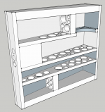
I attach a model showing it with 3x13mm ports. I've moved them more towards the middle as I believe it's bad to have the internal port terminus too close to any internal surface, and in the original it'd be very near the bottom. As it is, they are still quite close to the rear panel, should I try to move them again? I could possibly drill them in at a slight angle to keep them away more.
I've tried to keep the bracing to the golden ratio, but only a few are in reality. Should it be sufficient? You're seeing 9mm plywood and 18mm solid timber in this model. With all the bracing, port and driver volumes taken away we arrive at about the 1.95L required volume. I'd plan to stuff along the bottom section, mabye the top too, and heavily at the port end of the enclosure (though not in front of the ports naturally!). I think I'll need heavy acoustic foam behind the driver and mabye on the rear side of the front baffle too. Thick felt may also be us some use, just to line things?
Overall, this will be difficult to build, due to the small sizes of many pieces and the sloping front. Any input appreciated! Perhaps it's a complete non-starter for reasons I may have overlooked? I don't know, it seems it should work technically, but it 'looks' wrong!
Attachments
I was just going to say the same thing Chris. Also with slot loading the ports you'd get far more rigid cabinet walls. I say slot load them to the thin side and near the bottom of the wedge. As Chris has already pointed out the slot could be incorporated into part of the bracing and will also provide much less port noise than 3 smaller diameter round ports....
Hmm, I'm finding it hard to envisage exactly what you mean. I'm not sure how clear it is on my model but those 3 ports are drilled into a solid wooden block which will act as some degree of bracing. I couldn't reduce port noise without eating into more internal volume? I guess the slot is a little more volumetrically efficient though in an angular design.
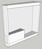
I've drawn what I think you're suggesting, but am probably wrong! That is a larger port incidently, it was just clearer to show this way. I think this type of port would be quite difficult for me to build as it'd involve having a broad slanted profile bit of timber/board. I don't think it's exactly what you're suggesting though anyhow.
Thanks for your input!
Attachments
Hmm, I'm finding it hard to envisage exactly what you mean. I'm not sure how clear it is on my model but those 3 ports are drilled into a solid wooden block which will act as some degree of bracing. I couldn't reduce port noise without eating into more internal volume? I guess the slot is a little more volumetrically efficient though in an angular design.
I've drawn what I think you're suggesting, but am probably wrong! That is a larger port incidently, it was just clearer to show this way. I think this type of port would be quite difficult for me to build as it'd involve having a broad slanted profile bit of timber/board. I don't think it's exactly what you're suggesting though anyhow.
Thanks for your input!
For an idea as to how to incorporate slot port(s) into the cabinet bracing scheme , take a look at any of the Fonken-esque enclosure designs at
Meet the Fonkens
FWIW, I'd imagine that the narrow end of your contemplated wedge design is not where you'd need the most bracing, so the port(s) could be accomplished with simple small panel(s), and full width braces might be overkill.
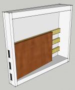
Ok, going by the Fonken bracing system I come up with something like the attached. Using thin timber beams and a panel of plywood to create 3 ports, they arn't any particular size this time.
I can see how this would in effect make the rear panel appear a lot thicker and more solid. I'm not sure how much it will do for the front, but I guess using a brace like I showed earlier will effectively tie the front to the extra solid back panel. Downsides however are that making ports long enough to have much bracing effect eats up a lot of internal volume. Also, they expand so far into the enclosure that they may be in the way of the rear side of the driver when mounted.
Is this what you were suggesting, or am I still thinking about it wrong? I can see how it works on the Fonken designs to add a lot of stiffness to the sides and hence the cabinet overall, but in mine I'm not sure it'd be so practical due to space limitations.
Attachments
Ok, going by the Fonken bracing system I come up with something like the attached. Using thin timber beams and a panel of plywood to create 3 ports, they arn't any particular size this time.
I can see how this would in effect make the rear panel appear a lot thicker and more solid. I'm not sure how much it will do for the front, but I guess using a brace like I showed earlier will effectively tie the front to the extra solid back panel. Downsides however are that making ports long enough to have much bracing effect eats up a lot of internal volume. Also, they expand so far into the enclosure that they may be in the way of the rear side of the driver when mounted.
Is this what you were suggesting, or am I still thinking about it wrong? I can see how it works on the Fonken designs to add a lot of stiffness to the sides and hence the cabinet overall, but in mine I'm not sure it'd be so practical due to space limitations.
I think you've got the general idea - of course how much volume the port panels/bracing consume would depend on your tuning calculations. Note that in most variants of the Fonkens, the slot ports throat are quite narrow, (i.e. in the case of the "milli" and "micro" as little as 12mm ) and incorporate a 90dg corner, which allows the spacers and/or slot panels to become part of lateral and/or front to back bracing. Placement of damping material is also important - it's important not to occlude the internal opening of the narrow port slots.
Of course, on boxes as small as these, it doesn't take a lot of mass to provide strategic bracing.
I've been using my test speaker (4ohm Monacor in 2L ported box) and am thinking that however I do it, I may need more port area. The test box has one 25mm port. Playing tones around tuning I get a lot of noise, which sounds like distortion, but it dissapears when you block the port. This is at a level where lower tones approach Xmax. I may need to make the box a little thicker to make up the volume to accomodate a larger port. How helpful is flaring port ends? I can potentially do both ends if I can fit a large enough port in, perhaps protruding from the top.
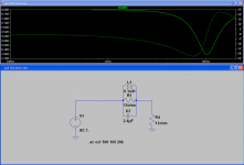
I've also been playing with notch filters. I know it seems a bit odd to use a passive notch when I'm building the amplifier myself, but I want to keep the electronics simple on this and the notch belongs to the speaker really. It is to tame the 10kHz peak. I'm currently testing one which gives about 15dB attenuation on the 4ohm version, made out of parts I have around. This seems like too much considering it will be used at least slightly off-axis and mounting near a wall is going to tilt the tonal balance away from the treble end as well. I think I'll use the one attached for a happy medium. I took the 12ohm speaker impedance from the plot on Monacor's site, which it shows as the value around 10kHz.
chrisb, you posted while I was typing, I'll come back to you!
Attachments
I'll try to find an optimum port area, location and type which doesn't compromise the internal volume too heavily. Perhaps there is a 'rule of thumb'? This driver is 30cmsq Sd and +/-2mm Xmax.
I think I know what you're saying about bracing. Once the panel size is small enough, there won't be enough energy from the driver to excite it. Am I correct in dividing the panels into long and thin areas? I had heard that a brace should divide a panel into smaller panels with higher aspect ratios, so have been trying to keep to that.
Whilst playing the speaker on the floor (angled up) but toward the middle of the room, I noticed that as I move towards the opposing wall, I gain a lift of the bass frequencies. I assume this is because I am then getting boundary reinforcement from both the floor and the wall? It is quite a desireable effect, not boomy at all, just fuller sounding. I then tried it on the bed but near to the wall, which yielded a reult more like being near the speaker on the floor, as one might expect, in effect getting just 1 boundary reinforcement.
Of course, I'm now wondering if there is a practical way to get that effect of 2 boundaries on the desktop! All I've come up with is if the desk is in a corner you can expect to get 2 walls reinforcement, to some degree at least. More eccentrically, if the enclosure had long ports protruding from them down to near the floor, this might give the same effect?! Thirdly, if you had an exceptionally large desk you might expect some reinforcement of bass from it, however I won't have. Any more practical ideas? Electronic bass boost is of course possible since the source is a PC, but is at the expense of excursion/available output
Ok, this seems like quite a good balance of elements. Featuring a larger dual slot port arrangement (7.2sqcm instead of 4sqcm) consisting of two 12x30mm port openings, with the construction intended to add stiffness to the enclosure too. The ports are on the inside edge at the bottom, to try to gain anything the desk boundary might add.
2 full braces and 2 partial braces (which can be cut from a third full brace). Spaced as much as possible to the golden ratio. With these and the larger port we are slightly lacking internal volume. Making the whole enclosure 2-2.5mm thicker brings it back up though. In practise, this may not be required as the internal wadding should also make the enclosure appear larger?
2 full braces and 2 partial braces (which can be cut from a third full brace). Spaced as much as possible to the golden ratio. With these and the larger port we are slightly lacking internal volume. Making the whole enclosure 2-2.5mm thicker brings it back up though. In practise, this may not be required as the internal wadding should also make the enclosure appear larger?
An externally hosted image should be here but it was not working when we last tested it.
Well, I have the drivers for these now and have built my little amplifier which will be used with them:
http://www.diyaudio.com/forums/chip-amps/168553-lm1875-miniature-desktop-amplifier-build.html
Today I started making a few rough bits with my jigsaw. I'll need to get everything straight with the router. I can already tell it's going to be a bit of a challenge, the rough (but quite heavy/solid) plywood doesn't make things easy! I plan to make a simple jig for cutting the angled parts to the same spec.
The impedance is a bit confusing. I have a simulation showing the predicted impedance plot of the driver in the box attached to this post. The impedance rise on this simulation is a lot more dramatic than the presumably measured one shown on the documentation for these drivers:
http://www.monacor.de/typo3/index.php?id=84&L=1&artid=4916&spr=EN&typ=full
The driver being in this enclosure shouldn't influence the top end impedance much should it? Which do I take to be true? I need to guage whether I will require a Zobel or not
I will keep you updated with the build in this thread. If anyone has any suggestions let me know, it's not too late yet!
Attachments
Last edited:
Just starting building these. I am building both simultaneously for this, so hopefully I don't make (and copy) any errors!
Here you can see the back (9mm ply) of the cabinet attached to the top and bottom angled sections of solid timber (spruce, probably). The one under is glued and clamped, using the offcuts to allow easier clamping. To the left is my angle cutting jig, used with a router fitted with a bearing cutter bit. The back of that 9mm ply has a roundover applied, the plan is to wrap right around these with maple effect vinyl covering.
I obtained some 12x15mm wood batton, which I will use to construct the bass ports. This means they will be slightly larger (15x28mm instead of 12x30mm). I did increase the depth by 2mm though, so I shouldn't be short on internal volume
An externally hosted image should be here but it was not working when we last tested it.
Here you can see the back (9mm ply) of the cabinet attached to the top and bottom angled sections of solid timber (spruce, probably). The one under is glued and clamped, using the offcuts to allow easier clamping. To the left is my angle cutting jig, used with a router fitted with a bearing cutter bit. The back of that 9mm ply has a roundover applied, the plan is to wrap right around these with maple effect vinyl covering.
I obtained some 12x15mm wood batton, which I will use to construct the bass ports. This means they will be slightly larger (15x28mm instead of 12x30mm). I did increase the depth by 2mm though, so I shouldn't be short on internal volume
If anyone has any suggestions let me know, it's not too late yet!
Have you considered a spiral horn?
http://www.diyaudio.com/forums/full-range/84026-cornu-spiral-copy-horn.html
An externally hosted image should be here but it was not working when we last tested it.
Cheers,
Alex
That's a cool design, I can see the advantages there. Aside from the horn loading you get a very well braced enclosure which sits quite flush to the wall. I think for me to get useful extension I'd need a horn nearly that size though, which I couldn't accomodate.
Today, I've added in the bass ports. These are 28x15mm each and 140mm long (to be 149mm long with the side affixed):
Starting to gain some rigidity, but still has a long way to go. The ply has quite a high natural resonance, which I believe is desirable in fullrange designs.
First brace going in next, will keep you updated
Today, I've added in the bass ports. These are 28x15mm each and 140mm long (to be 149mm long with the side affixed):
An externally hosted image should be here but it was not working when we last tested it.
Starting to gain some rigidity, but still has a long way to go. The ply has quite a high natural resonance, which I believe is desirable in fullrange designs.
First brace going in next, will keep you updated
That's a cool design, I can see the advantages there. Aside from the horn loading you get a very well braced enclosure which sits quite flush to the wall. I think for me to get useful extension I'd need a horn nearly that size though, which I couldn't accomodate.
Today, I've added in the bass ports. These are 28x15mm each and 140mm long (to be 149mm long with the side affixed):
An externally hosted image should be here but it was not working when we last tested it.
Starting to gain some rigidity, but still has a long way to go. The ply has quite a high natural resonance, which I believe is desirable in fullrange designs.
First brace going in next, will keep you updated
will be looking forward to the pictorial progress... gychang
- Status
- This old topic is closed. If you want to reopen this topic, contact a moderator using the "Report Post" button.
- Home
- Loudspeakers
- Full Range
- Unusual design for desktops - The Wedge