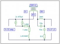
The 'T' bass circuit is attached in open baffle form.
A first construction using the values shown will give an idea of its capabilities.
The 2x 470uF (low ESR electrolytic) capacitor tunes the choke to the baffle/rear reflection peak which can become obtrusive around 100-120Hz. This can allow an OB to be moved further back into a corner. Try different capacitor values to adjust the 'cut' frequency.
The cut runs from around/above driver Fs and becomes maximum at the baffle/room corner SPL peak frequency. The resistor in series with the capacitor controls the degree of cut at this frequency.
The choke controls the voltage step-up which arises below/around driver FS where the driver impedance becomes high, and often fails to return to nominal at low audio frequencies. The choke value can be increased to reduce the boost frequency, but this depends on baffle (U/H frame etc.) size. It is the slope with respect to roll-off which is most important, not just the boost frequency itself, for this circuit is acting in series with the driver(s), and it is the driver(s) which limit the 'boost' capabilities the step-up ratio can provide. Choosing 'too low' a choke value will produce a kinked boost resultant which no longer optimally matches the driver/baffle roll-off. The resistance of this choke should also be low to allow LF 'voicing' via resistor adjustment. If the choke does not have a low resistance, then the resistor in series with it may be omitted.
The resistor in series with the choke plus the resistor in series with the capacitor together control the degree of boost/cut arising to balance the first half cycle transduction losses against driver resonance derived SPL increase. There is an initial phase coherent series choke induced boost to counter driver subtraction of first half cycle energy, which becomes stored within the suspended cone and contributes towards resonance, followed by damping due to the series tuned C+L input circuit which limits continuing energy input into the loudspeaker system at its resonant frequency. Resistor values which are too low will provide a response with too much first half cycle emphasis - hence values should be individually selected to suit the driver cone mass, baffle form, Qes etc., also to suit personal preferences, because a slightly over emphasised boost might actually be preferred to compensate for some unavoidable loss at the very lowest of reproducable frequencies.
The line transformer may be between 250 and 500VA, between 2x 18V and 2x 40V depending on driver choice, and with its mains voltage primary left OC. The lower ratings would suit one or two Aplha-15As in parallel, the higher ratings larger Pro drivers. Of most importance is obtaining a transformer with low secondary winding resistance, which generally means toroidal types.
The series output choke should be chosen to suit the selected LF driver; 2mH being shown here as a mid value starting point. Its value may be lower with parallel drivers, higher for those having good MF sensitivity, or may even be omitted with drivers already having significant voice-coil inductance.
The 10uF in parallel with the output choke makes it act like a parallel tuned circuit to introduce roll-off in the typical 1-2kHz breakup region. The final series connected R+C components form a Zobel to counter driver impedance rise with frequency.
The driver is your choice. I have had feedback of the circuit working well with several different types.
The amplifier MUST be a SS NFB type with good damping figure. It should be 4 ohm continuous rated for use when this circuit drives an 8 ohm driver on an OB, and 2 ohm continuous rated when two 8 ohm drivers are driven in parallel. If of sufficient quality this same amplifier may also feed the wideband driver via a series capacitor, say 47 to 220uF, though with a damping resistor connected in parallel with the wideband driver voice coil, say 8.2 ohms accross an 8 ohm nominal driver. Once the wideband driver has this damping resistor connected it is easy to reduce its sensitivity by inserting a resistor in series with the capacitor, say 2.2, 4.7 ohms etc., maybe with a 470nF to 1uF in parallel with the series resistor to maintain overall balance if a supertweter is not being used.
The T-bass circuit may also be used for IB too - between amplifier and crossover though without the series output choke. The kind of energy balancing AF response this 'T'-bass circuit produces *cannot be matched by EQ*, because EQ does not act with the loudspeaker during waveform time.
Cheers ........ Graham.
Attachments
Only those who actually construct and listen to this circuit will appreciate the advantage it provides.
It is possible to increase OB output at LF by using a high 'Q' LF driver, but the amplitude gain arises due to driver resonance and passive crossover interaction, typically in the Fs to 2x Fs frequency range, but below Fs the relative output then falls away much more sharply as a result.
The 'T'-bass circuit provides a similar lift, but the drive is more phase coherent with input, and with a decent transformer the boost below Fs is maintained down through 20Hz.
I here show force related driver current via a representative woofer equivalent circuit, because driver reactance renders a voltage waveform viewed in isolation less directly relevent.
Cheers ........ Graham.
Attachments
And some current traces via a representative woofer equivalent circuit.
Voltage responses are not shown here because it is the current which energises the voice coil, and current becomes phase shifted by driver reactivity. As illustrated here by the direct connection to a voltage output amplifier.
If too much energy transduced via an initial current peak becomes stored a LF driver, then the reproduction becomes muddied. On the other hand current drive does not provide enough 'first cycle' drive to accurately amplitude drive the cone mass.
Adjusting component values adjusts the level of first cycle boost, slope, peak and dip frequencies etc.
Cheers ...... Graham.
PS. If your browser won't resolve this - try fullscreen (the F11 key ) or right click and save the picture to desktop then (double)left click to open with the normal Windows viewer.
Attachments

Thanks for the explanation to T-bass Graham.
I love your circuit, it's working well on my test baffles (4 x 7" woofers, series-parallel).
Question: what happens if the transformer is too small?
Mine are 100VA and I can't detect any obvious problems.
Simon
ps - drums, in particular, sound fantastic with this circuit on an open baffle speaker
I love your circuit, it's working well on my test baffles (4 x 7" woofers, series-parallel).
Question: what happens if the transformer is too small?
Mine are 100VA and I can't detect any obvious problems.
Simon
ps - drums, in particular, sound fantastic with this circuit on an open baffle speaker
richie00boy said:Any details or pics of your OB setup Simon? Hope to see it at the 08 fest")
Hi Rich,
Any more subwoofers on the go?
Here's my OB story so far:
http://www.diyaudio.com/forums/showthread.php?s=&threadid=128015&highlight=
I'm afraid most of it is me thinking out loud and learning! But there are a few pics. More to add actually as I've just been tinkering.
T-bass is what it's all about though, as you'll see if you read it through.
Simon
Hi Zen Mod,
Give them a try - they sure won't be saturating !
A single winding resistance of circa 0.1 ohm is desirable, at 0.2 ohm some LF loss of attack becomes just detectable, and even up to 0.5 ohm will work well - though maybe with different resistor/capacitor/choke values.
Hi Sy,
Glar to hear you are enjoying the improved OB bass.
Your 4 driver series/parallel will also be improving efficiency, means you get decent output without too low a load on the amplifier.
When the transformer is too small it just does not work as well as a larger one will, and if of too low a voltage it might saturate and cause an amplifier to clip.
If yours is working fine, just make sure you go as big as you can if you upgrade.
Cheers .......... Graham.
Hi Simon,
Many LF drivers beam or resonate or suffer cone breakup modes before they roll off. This can cause a peak which interferes with mid driver output. T
The capacitor forms a parallel tuned circuit with the series inductor. This can cut output by 30dB at the peak frequency and or assist LF driver roll-off.
Very easy to try. To broaden the range of frequencies being cut, but also make the degree of cut less shallow you could try a resistor in series with the capacitor, say 1 to 4.7 ohms.
Cheers ......... Graham.

You're not thread jacking at all.
Only when those who have grown up with 'boxed' loudspeakers,
or when those who introduce too much phase change at the crossover frequency by cutting LF above say 70 to 100Hz to equalise for OB roll-off, instead of some cut above plus some boost below
will baffle augmentation drivers better blend in with the mid or widerange drivers.
About ten years ago I designed a discrete LF boost circuit I called 'e'-bass.
It had adjustable boost below 100Hz ( 0 to +20dB at 20Hz ) and the boosted output remained 'in-phase' at all frequencies and all boost levels between 15Hz and 20kHz, but it did not have the capability of increasing the first half cycle, as does this 'T'-bass. This later circuit can counter driver losses to make drums and plucked basses sound so much more lifelike.
Had I built this circuit first I might have built a first half cycle boost into the 'e'-bass, but alas I am well past my sell-by date now.
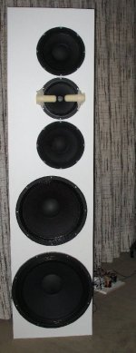
Somehow I lost the upload of my last post which included a pic of my own 'T'-bass driven LF drivers - one Beyma SM-115N and one Eminence DeltaPro-18A in parallel. The entire panel is 6ft high and driven by a single 100W-4R GEM amplifier which proves to be one ohm capable..
Cheers ......... Graham.
Only when those who have grown up with 'boxed' loudspeakers,
or when those who introduce too much phase change at the crossover frequency by cutting LF above say 70 to 100Hz to equalise for OB roll-off, instead of some cut above plus some boost below
will baffle augmentation drivers better blend in with the mid or widerange drivers.
About ten years ago I designed a discrete LF boost circuit I called 'e'-bass.
It had adjustable boost below 100Hz ( 0 to +20dB at 20Hz ) and the boosted output remained 'in-phase' at all frequencies and all boost levels between 15Hz and 20kHz, but it did not have the capability of increasing the first half cycle, as does this 'T'-bass. This later circuit can counter driver losses to make drums and plucked basses sound so much more lifelike.
Had I built this circuit first I might have built a first half cycle boost into the 'e'-bass, but alas I am well past my sell-by date now.
Somehow I lost the upload of my last post which included a pic of my own 'T'-bass driven LF drivers - one Beyma SM-115N and one Eminence DeltaPro-18A in parallel. The entire panel is 6ft high and driven by a single 100W-4R GEM amplifier which proves to be one ohm capable..
Cheers ......... Graham.
Attachments
Hi kristleifur,
Look at the 'T'-bass circuit.
At low bass frequencies below driver Fs we can forget the capacitor and note that the choke plus transformer circuit approximates a 2x step-up of amplifier output voltage without phase change. This however is where developed LF driver impedance is higher due to driver Q such that the amplifier loading is not as high as a nominal impedance ratio transform would suggest, and thus the continuous power loading is not x4.
Above Fs we can forget the choke and see that the capacitor shorts the transformer, which makes it pass higher bass frequencies without phase change, except for the series R, also the driver and Zobel loading.
The C and L parallel tune via the low impedance SS amplifier such that the 'ground' reference impedance 'seen' by the transformer increases, thus the amplifier induced transformation of output voltage becomes decreased, and the C + L values may be chosen to counter the driver/baffle/room peak/slope which normally limits 'woofer on a baffle' reproduction.
Unfortunately the C and L series tune with respect to the amplifier to become an additional partial load, but this is at the same frequency where the transformer output has been reduced, also where the loudspeaker drive impedance has become increased so that the woofer stores/releases less parasitic energy.
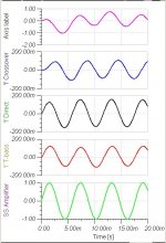
Thus the 'T'-bass circuit increases output below driver Fs, and cuts it above. It produces baffle slope correction through low and mid bass without introducing the phase change normally generated either by an EQ and/or crossover circuitry, such that hand-over to a widerange driver can be more phase coherent and without the crossover induced 'slow bass' effect which so often impairs woofer plus widerange OB pairings (as illustrated in the 170Hz trace).
The 'T'-bass works.
And it works with enclosures; I recon it will work especially well with home IB and rear deck car loudspeakers.
It could even lead to better lower frequency output from already existing bookshelf loudspeakers, though others will need to try this.
It is a simple circuit, but explaining its operation is not easy, so I trust this helps.
Cheers ....... Graham.
Look at the 'T'-bass circuit.
At low bass frequencies below driver Fs we can forget the capacitor and note that the choke plus transformer circuit approximates a 2x step-up of amplifier output voltage without phase change. This however is where developed LF driver impedance is higher due to driver Q such that the amplifier loading is not as high as a nominal impedance ratio transform would suggest, and thus the continuous power loading is not x4.
Above Fs we can forget the choke and see that the capacitor shorts the transformer, which makes it pass higher bass frequencies without phase change, except for the series R, also the driver and Zobel loading.
The C and L parallel tune via the low impedance SS amplifier such that the 'ground' reference impedance 'seen' by the transformer increases, thus the amplifier induced transformation of output voltage becomes decreased, and the C + L values may be chosen to counter the driver/baffle/room peak/slope which normally limits 'woofer on a baffle' reproduction.
Unfortunately the C and L series tune with respect to the amplifier to become an additional partial load, but this is at the same frequency where the transformer output has been reduced, also where the loudspeaker drive impedance has become increased so that the woofer stores/releases less parasitic energy.
Thus the 'T'-bass circuit increases output below driver Fs, and cuts it above. It produces baffle slope correction through low and mid bass without introducing the phase change normally generated either by an EQ and/or crossover circuitry, such that hand-over to a widerange driver can be more phase coherent and without the crossover induced 'slow bass' effect which so often impairs woofer plus widerange OB pairings (as illustrated in the 170Hz trace).
The 'T'-bass works.
And it works with enclosures; I recon it will work especially well with home IB and rear deck car loudspeakers.
It could even lead to better lower frequency output from already existing bookshelf loudspeakers, though others will need to try this.
It is a simple circuit, but explaining its operation is not easy, so I trust this helps.
Cheers ....... Graham.
In my Open Baffle Speakers thread Lynn Olsen asked about 'T'-bass impedance and its influence upon the driver - re driver Q etc.
Following on from the traces above where the standard 9mH-68uF crossover is shown inducing voice coil current delay (slow bass), also in relation to my statement that the 'T'-bass circuit can improved first cycle drive and thus compensate for losses due to cone (mass) inertia, I have here added a pink trace which shows voltage development across the transformer during waveform time.
This shows that voltage reduction builds up out of phase at this frequency (170Hz), tuned by the L, the C *and* the series connected driver. The delayed reduction allows driver current to establish adequate cone movement for initial waveforms.
The current/voltage amplitudes must be viewed with an understanding that they are not literal due to relevent phases not being coherent, but at least component values can be tuned/damped for optimum current drive.
Cheers ........ Graham.
Attachments
This circuit is very interesting - I was thinking about something similar to Manzanita 12 - but the drivers are not easy to get here. I will most probably use a small fullranger instead of a tweeter.
My questions are two - how should I connect the crossover? Between amp/t-bass? The other is - which kind of driver works best - with regard to Fs and Qts?
My questions are two - how should I connect the crossover? Between amp/t-bass? The other is - which kind of driver works best - with regard to Fs and Qts?
Amp > T-bass > x-over I believe is how Graham recommends doing it.
My bass drivers are QTs = 0.4, FS about 40hz, 60cm baffles (30 + 15cm wings) and I get strong bass to about 50hz using T-bass. My series coils are high DCR, which effectively raises driver QTS.
I would *think* a slightly higher Qts (0.6-0.7) would be ideal and a low FS (<30hz) is best to get the deepest bass available from an open baffle. I also think a bigger, single driver would be best.
An 18" with FS of 20hz and Qts of 0.7 would probably deliver superb bass, as long as it matches with the mid/top!
Hope this helps a bit.
Simon
Hi all
I am also rebuilding my dipole speakers. I am using a "baffleless" 18" unit with Fs = 29Hz and Qts of 0,6. This is the driver in question. I actually have four pieces available and have them set up much like these (picture by member MisterTwister). Equalization is active: a shelving low pass (with f1 at 20Hz and f2 at 90Hz, for a total of 12dB attenuation between both frequencies) and also 12dB LP at 90Hz. On top of that a visaton B200 - also on open baffle - crossed over at about 100Hz, 12dB HP.
The set sounds nice (even baffleless the woofers apparently go low enough), but I will do like SimontY and buy a measuring microphone and use ARTA to optimalize things. SimontY: thanks for the link and suggestion!
With the above described configuration in mind I was thinking what the advantage of the T-bass circuit would be. I think that the line level equalization is doing the same thing, technically speaking, but I read some comments by Graham that T-bass improves the interaction between amplifier and woofer.
So, Graham, do you have any wise words for the application of T-bass to the above circuit?
Erik
Hi Sy,
Thank you for correctly answering Pelanja's question.
All wound components should be as low resistance as can be afforded.
Hi Erik,
From the specification that driver would appear to be a good choice, however the roll surround would not be my choice for OB or free field working (absorbs/ modifies energy), and going from 18" to 8" in one go seems too big a step.
Might be better with say a 12" in between, or 2x 10" in D'Apollito, which I use with two large LF drivers per channel.
I would not mount like those shown either because they do not displace maximum air as is necessary at very low AF; better to have them beside each other, or one above the other.
If I read correctly you already have one low pass at 20Hz and another at 90Hz to cross-over to the B200.
Also a direct amplifier connection which will cause the LF drivers to store energy and release same in its own time wrt amplifier drive.
Yes the bass will be there but it is phase shifted (delayed) wrt B200 drive through the crossover region, and trapped energy muffled/confused due to direct low-Z amplifier connection.
Using an electrical low pass filter to implement EQ introduces a LF phase delay wrt the main driver waveform at frequencies above its turnover (20Hz) frequency.
Whereas using amplitude lift below the crossover frequency can provide better phase coherence.
The T-bass provides phase coherent LF lift, cuts around the room corner/ driver LF peak, provides raised source impedance in series with the driver which reduces energy storage; thus reduces filtering requirements which convenionally leads to 'slow'/heavy bass reproduction and much reduces the 'masking' effect at LF caused by direct amplifier/ driver connection.
There is a need to rethink crossover design in order to fully implement the T-bass (normal software approaches will not work - if they ever did anyway because driver characteristics have much greater impact anyway), but once working correctly it can be heard as a most worthwhile improvement which EQ alone, or any kind of enclosure simply cannot match.
Give it a try, for your own ears will provide a far better personal comprehension than I can via this thread.
I would love to see someone else taking the phase coherent transformer method forwards now, as I am having to take a back seat due to health reasons.
Simon - yes at LF a large driver without a baffle is better than a small driver on a baffle having the same cross sectional area. Just saying that in case you get round to building another OB.
Cheers ............. Graham.
- Home
- Loudspeakers
- Full Range
- 'T'-bass drive for OB LF drivers.