I have in mind a couple of very simple circuits with transformers I would like to mess around with in simulation before trying. I would prefer if the spice simulator contained a loudspeaker to sim, but this is not entirely necessary. The ability to simulate a transformer would be, however.
The demo version of LSPCAD for Adire drivers allows you to simulate passive crossover networks, but lacks the ability to use transformers. Hence my turning to circuit simulators.
Any suggestions where to look? I never used a spice simulator before.
The demo version of LSPCAD for Adire drivers allows you to simulate passive crossover networks, but lacks the ability to use transformers. Hence my turning to circuit simulators.
Any suggestions where to look? I never used a spice simulator before.
Hmm Jan,
Me think there is something more to say about PSpice in the context of LS simulation. PSpice by itself is nothing more then a numeric solver for differential equations.
The syntax of it is kind of a programming language. You have to understand this syntax to be able to really know what you are doing and to model the things you want to simulate, like loudspeakers..
Nowadays the are a lot of Pspice simulators which have an integrated schematic capture front end that automatically generates the Pspice listing in the background for you and are easy to use.
Kelticwizard, to get your feet wet, here you can download a free student/evaluation version of Microcap: http://www.spectrum-soft.com/demoform.shtm It is limited to 50 components but that is more than sufficient to simulate what you intend. Besides this software get a good introductory textbook about PSpice.
I myself used this software some 10 years ago to simulate a PR loudspeaker box, when no ready made LSsim-software for that was available. BUT to be able to build a model you have to fully understand the mathematics behind it. I have posted some years ago an electro-mechanical model for LS simulation on this board. For that use the search function
PSpice is not easy to get started with but at least it is great fun. Good luck!
Cheers
janneman said:Have you searched???
Jan Didden
I have searched both Google and this board. In fact, over the years I have paid attention to various threads where people were starting out in Spice, since I had in the back of my mind the idea that I would like to try it someday.
However, there seemed to be so many demos and programs to get started, I thought I would throw it out to the board what I was primarily interested in finding and see which would be the best choice to go.
Just like there are many free/cheap speaker simulation programs, the desirability of which depends on what the user is primarily interested in finding.
You can simulate transformers in any spice program, including SwitcherCAD, free from Linear Technology. SWCAD has no limitations and there are a bunch of example circuits that show how to do things like implement transformers.
You use two inductors and add a spice directive that contains the coupling coefficient between the two. Of course, the inductors are ideal, so you will need to figure out a good model for your transformer and add the necessary parasitic elements either as properties of the inductors or connected to them. THAT is ALWAYS the hardest part when using spice.
A lot of people have tried modeling transformers before you so do a web search and see what is out there. You might get lucky and find a decent model that you can tailor to your specific part by making a few simple measurements.
I_F
Attachments
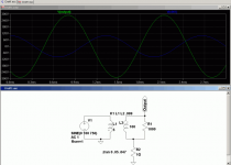
The image in the previous post shows how a transformer is created in SWCAD (and any other spice, as far as I know). The blue trace is the input voltage. The K1 statement contains the coupling coefficient between the two inductors. What you can't see on the schematic is the parasitic series R and parallel C and R for each of the inductors.
A tapped transformer coil would simply have a coupling coefficient statement like K1 L1 L2 L3 .99999
The 1 G resistor to ground on L2 is necessary because each loop in a circuit has to have a DC connection to ground in order for spice's solver to work. Using 1 Gohm ensures that the connection has no effect on the circuit behavior.
You can model core nonlinearities also. The help file that comes in SWCAD has this to say:
There are two forms of non-linear inductors available in LTspice. One is a behavioral inductance specified with an expression for the flux. The inductor's current is referred to by the keyword "x" in the expression. Below is an example in a netlist.
*
L1 N001 0 Flux=1m*tanh(5*x)
I1 0 N001 PWL(0 0 1 1)
.tran 1
.end
In the above example, I1 supplies a unity dI/dT so that the inductance can be read off as the voltage on node N001.
There other non-linear inductor available in LTspice is a hysteretic core model based on a model first proposed in by John Chan et la. in IEEE Transactions On Computer-Aided Design, Vol. 10. No. 4, April 1991. This model defines the hysteresis loop with only three parameters:
name | parameter | units
-----+-------------------------+------------
Hc | Coercive force | Amp-turns/meter
Br | Remnant Flux Density | Tesla
Bs | Saturation Flux Density | Tesla
The upper and lower branches of the hysteresis major loop are given by
H + Hc
Bup(H) = Bs · --------------------- + µ0·H
|H+Hc| + Hc·(Bs/Br-1)
and
H - Hc
Bdn(H) = Bs · --------------------- + µ0·H
|H-Hc| + Hc·(Bs/Br-1)
These functions are plotted in following figure. Hc and Br are the intersections of the major hysteresis loop with the H- and B-axes. Bs is the B-axis intersection of the asymptotic line, Bsat(H) = Bs + µ0·H, approached as H goes to infinity.
The initial magnetization curve is given by
Bmag(H) = .5 · (Bup(H) + Bdn(H))
Minor loops are obtained by various translations of the above equations per the cited reference. The core's absolute and differential permeabilities are a function of H and the history of values of H. The plot below shows the path taken by an asymmetrical minor loop for a typical power ferrite(Hc=16 A-turns/m, Bs=.44T, Br= .10T).
In addition to the core property parameters Hc, Br, and Bs, mechanical dimensions of the core are required:
name | parameter | units
-----+----------------------------+-----------
Lm | Magnetic Length(excl. gap) | meter
Lg | Length of gap | meter
A | cross sectional area | meter**2
N | number of turns | --
Note that if specifying a non-zero gap the magnetic field, H, is not proportional to the current in the windings. LTspice solves for the magnetic fields in the core and gap under the assumption of uniform cross sectional area and thin or uniformly distributed gap.
Below is an example that shows inductance vs. current for L1, an inductor wound on a gapped core. You can read out the inductance as V(n001) since current source I1 supplies a unity dI/dt. The core follows the initial magnetization curve, so you can see that the permeability first increases from the initial value as the current is ramped and then drops as it saturates. Since the gap makes the inductance insensitive to the exact permeability of the core, you have to really zoom in on V(n001) to see that it does increase. The peak is when H inside the core is equal to its Hc.
*
L1 N001 0 Hc=16. Bs=.44 Br=.10 A=0.0000251
+ Lm=0.0198 Lg=0.0006858 N=1000
I1 0 N001 PWL(0 0 1 1)
.tran .5
.options maxstep=10u
.end
You'll find that using spice is the easy part. Modeling components accurately is the hard part.
I_F
Pjotr said:Hi
LTspice, or better Swichcad what it is actually named, is also an option. But Microcap has a much better user interface and is easier to get on the run IMO.
But whatever you choose, a good textbook about PSpice is mandatory to stay on the road.
Cheers
Last time I looked, Microcap cost money... SWCAD is FREE! A good feature for audio maniacs is the ability to use .wav files for input and output.
Tuinenga's book is good, but somewhat dated by the lack of schematic capture. It does a good job of pointing out some pitfalls and shows how to do some things that can be tricky if you don't know a lot about spice.
I_F
I appreciate your help so far, but I am having some trouble getting started.
So far, I have found out from others that a netlist is sort of a word description of a circuit that a computer can understand. I'm not sure if I need a netlist, or how to make one.
This is supposed to be schematic capture software, but I did not see any provision to capture the schematic just posted. Nor did I see any provision just to import the AC source for use in a different circuit, at least not easily.
You open up this program, see a blank screen, click new schematic, then what? The help files are less than helpful, especially when they illustrate taking something from a "boost" file which does not exist on the program.
This program looks like something that can help a great deal if I can just figure out how to get my feet wet. I don't mind experimenting around once I can start making things happen on the xreen, which I don't seem to be able to do right now.
The entire purpose of this project is to develop a simple tuned circuit to attach to an output transformer to make it behave in certain ways. Given the fact that series LC circuits develop nulls, (short circuits ) at resonance, I thought a little work on the computer would be helpful before i started. If I cannot simulate a loudspeaker on the schematic, even just using an 8 ohm resistor and then fine-tuning by experimentation would suit my purposes on this project.
If it is not asking too much, I crudely drew up a simple circuit in MSPaint and wonder how you can go about putting this into SwitcherCAD and measuring the voltage and amperage from the open side of the transformer. Would that be at all possible?
Attachments
Pete you draw the schematic in the schematic editor of the software (SWcad or Microcap or whatever), so unfortunately you have wasted the effort of doing it in paint
It's pretty easy to draw the schematic once you get going. There's usually a button along the top somewhere for you to select components like passives and semiconductors.
I use an ancient version of Microsim. I tried SWcad for a brief moment, but I found it a little harder to use and I couldn't be bothered at the time.
I might have a look at Microcap.
The demo version of ORCAD/P-SPICE can be had for free but it is limited to 50 elements. The circuit capture function is quite easy to do. If you can't get it from ORCAD themselves I can send you a copy of the CD (it actually says: "Copying of this software is welcomed and encouraged !").
Regards
Charles
Regards
Charles
Richie:
No biggie. If using schematic draw is as easy as using Paint, I will have learned a valuable thing. I'll be starting the schematic draw later today to see what happens.
Pete you draw the schematic in the schematic editor of the software (SWcad or Microcap or whatever), so unfortunately you have wasted the effort of doing it in paint
No biggie. If using schematic draw is as easy as using Paint, I will have learned a valuable thing. I'll be starting the schematic draw later today to see what happens.
Unfortunately, I am still having trouble.
I got the AC source by opening audioamp and starting a new schematic above it, then dragging the AC source from audioamp to that separate space.
I wanted to avoid getting the transformer by making two inductors, because then I would have to go to coupling coefficients and would complicate things. So I went to another file with transformers in it, but cannot move the transformer to the "audioamp" file where I am building the new schematic, above and separate from the already existing audioamp file. After my new schematic was complete, I planned to copy it to a new file.
How do I capture an existing tranformer in a separate file and import it-just the transformer, not the rest of the circuit-to a different file?
I am using switchercad, but they have a limited number of things to plug into the draw from the top "browser" line. A transformer is not among them, so I need to know how to import a transformer from another file in switchercad to avoid using a double inductor and coupling coefficient.
kelticwizard said:I am using switchercad, but they have a limited number of things to plug into the draw from the top "browser" line. A transformer is not among them, so I need to know how to import a transformer from another file in switchercad to avoid using a double inductor and coupling coefficient.
I don't understand the issue, this is how transformers are done in spice.. To get the transformation ratio right select a reasonable inductance for the primary (say 25H - 50H for a 3K primary) and to get the secondary inductance divide this by the square of the turns ratio. Set K=1 (coupling coefficient) and if you want to simulate leakage inductance add an inductor in series with the primary of an appropriate number of mH.. (This generally is easier to manage and results in less calculation overhead.) This should suffice for most applications.
Let me spell out the problems I am having on this maiden voyage, because they might not be clear from my previous posts.
I go to swither cad. I want to analyze the circuit on the previous page drawn in Paint.
A) Where do I get the AC source-how do I draw, or from where do I import? I would like it to be 10 V, 1.25 amps.
B) I don't think I'll have trouble entering the resistor and capacitor
C) Where do I get the audio transformer to put into the drawing. Do I draw it, or do I import it from the Educational circuits. How do I import it-I tried drag, I tried move, I can put a dotted box around the Xformer and move it around it's own circuit-but cannot move it to the file which contains the circuit I am building.
I have gotten advice that it is easy to draw a circuit, but with this simple circuit I see no way to get an AC source or a transformer, and that is half the circuit.
- Status
- This old topic is closed. If you want to reopen this topic, contact a moderator using the "Report Post" button.
- Home
- General Interest
- Everything Else
- Free Spice Or Cheap Spice Simulator-Where To Start?