If you don't mind the dummy asking, what kind of capacitors are that?
In order to save space they used double electrolytics for two of the three rail voltages (IIRC, I would have to open the thing to be sure which rails used those). Just think of a lower-voltage and higher-capacity version of the ones that were once fashionable in older tube gear.
Regards
Charles
Hi jacco,
Charles' explaination is right, but I'm going to try and make it more clear.
A dual section cap as in those Carver amps was like an old time multi section capacitor. They use the common outer case as ground and had two sections inside. From the outside it simply looks like a radial can capacitor, but has two positive terminals and case ground terminals.
I wonder what the capacitance between sections was. In a Carver, it may have allowed noise to bleed between supplies.
Hi Charles,
The lower two rails. 31 V and 60 V. The 118 V rails used the large can caps on their sides.
All, be careful with the supply voltage adjustment on these. The supplies ran close to the maximum voltage rating on the supply caps. The adjust control can get intermittent. Do not attempt to adjust unless you know exactly what you are doing and are prepared if the supply goes high. You do not want the supplies to go high!
-Chris
The dual cap used in the PM1.5 is certainly a rare bird - one section is 2200uF@50v and the other half is 2200uF@80v. Total unobtanium, and after kludging many with messes of hotmelt glue,cable ties and more standard caps, I finally made a little PCB to retrofit. Other Carvers seem to have unobtanium bits as well - The PM1400 has a little regulator/triac driver board that catches fire and uses a little Harris offline reg chip called a HV2405 and a half opamp/half comparator chip called an MC3405 - both gone the way of the dodo. The PT1250 used a couple of obtainable but bloody expensive BJTs in the SMPSU - luckily you can rip them out, along with the drivers and a pile of other bits and use a couple of modern IGBTs (4PC50UD or whatever) and they work fine. The cheesiest thing in the PM1.5 is the little $2 model shop motor that drives the fan (and whines like crazy when it whacks out its bearings).
M
M
Hi mobyd,
That thing is the easiest to replace. Small computer type fan without a speed regulator. The caps may go open in the fan supply. Don't forget how old these units are, they are allowed to fail.
-Chris
That motor isn't too bad. A lack of maintenance will allow the bearings to fail. I note that several other devices use a similar fan.The cheesiest thing in the PM1.5 is the little $2 model shop motor that drives the fan (and whines like crazy when it whacks out its bearings).
That thing is the easiest to replace. Small computer type fan without a speed regulator. The caps may go open in the fan supply. Don't forget how old these units are, they are allowed to fail.
-Chris
10 or so years ago, there was a Bob Carver interview,
in Audio magazine.
told them , that the first amp he made, was in a coffee can.
Said he had no money for a transformer, just ran the electric,
from the wall to the diodes , to the output devices-
Also had the nerve, to take his amp to the McIntoch clinic.
the Mc man told him
"this is the most powerful amp i have ever tested".
(350+ watts)
most of Bob's inovations, can be found in,
books about electronic instruments-
2360
Attachments
![bob-carver1[1].jpg](/community/data/attachments/72/72626-07d5bd97780330b50e74b54abe5b77fa.jpg)
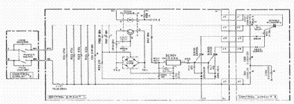
Here's an example of Yamaha's X-Power circuit, an infringement of Bob Carver's patent.
The piano motorcycle company used the "X-Power" in a few 1981 amp models, stuff i saw and heard at the time. (although a 21 year old marine knows squat didly about hand-to-circuit combat)
The triacs are switched by a Sanyo manufactured ig04080, the transformer primaries and ground connections are in the upper and bottom corner on the right side of the centre board.
150 watts in 4 ohms from only two 120 watt Pd output devices.
These amplifiers were only available for a short while, Bob Carver sued Nippon Gakki successfully, afaih.
Notte bade for a commercial marketing guy.
I remember a Carver amp you can rip dozens of green and black Toshiba 2SA1302/2SC3281 out.
Attachments
Hi Kahuna,
The A-760x is a good amp. A later design, it sounded better. The casework was less expensive to make.
Hi Jacco,
You may be thinking of a 500 or something early along those lines. Almost all plastic transistors in a Carver were 2SA1302A and 2SC3281A. Even the Lightstar. Earlier metal outputs were replaced with MJ15024 and MJ15025 types.
-Chris
anatech said:Ways to kill a Carver:
Run mids and or highs only (locks the commutators up).
Run an extension cord or poor circuit (voltage falls and supply draws more to compensate).
Run off a small gas generator. (love that, both amp and generator become extinct).
Plug into 550 VAC (flames will cut TO-3 cases and bottom cover)
Let moron service it. (most people refuse to read the service manual).
Chris, can you explain the failure mode that ensues when a Carver amp gets hooked up to a small gas generator? It would be interesting to know the mechanisms of failure for both the amp and the generator.
Thanks.
Hi solderhead,
That's easy if you consider how a Carver amp operates.
The Carver type power supply does not hold a huge amount of energy in reserve. It holds just enough to do the job. Therefore the standby current is very small, little heat being dissipated. Once a signal comes along, the required energy is almost immediately draw from the AC supply. This is because the energy is regulated right at the AC input. As the regulating circuits sense a supply voltage drop, they increase the conduction angle on the triac which results in more current being draw. It does this very quickly in time with the music. The fans on a PM 1.5 sit on their own winding and unregulated power supply, so are speed controlled by how hard the triac is turned on. You can hear them going to the music.
What I'm getting at is that the current demands are very immediate from the AC supply. Most times people load these amps down at 4 ohms or lower (even though they shouldn't). Now, a gas generator's output is controlled a little by changing the field current in the generator. The problem is that it can't track the Carver's current demands because they are so quick. The generator overshoots (voltage too high). This tends to cause a decrease in current in the Carver. The generator then undershoots (voltage too low) so the Carver draws more current. The cycle is like a low frequency oscillation - depending on the generator.
At some point the voltage gets high enough to damage the Carver, or low enough to damage the Carver and generator (at low voltage the Carver draws much higher than normal current). How would you like to have a mixer on the same circuit for that ride? All source devices get severely abused as well. Anyway, anything can happen once this gets out of control. I have no doubt that there are generators that can put up with this. The problem is that everyone buys the least expensive generator they can find.
Extension cords are also very bad for these amps if they are too thin or the run is too long. High voltage drop = high current = blown fuse at some point. A possible shorted triac means that when the fuse is replaced the amp may go full current with extremely high voltages inside. This is not pretty.
-Chris
thanks! i am familiar with the immediacy of the current demands caused by these sorts of amps (i've seen them dim the lights to the music), and the dramatic effects on voltage that a subtle change in line resistance can cause under extreme current demands (why extension cords are a very bad idea).
yes, its easy to see why undervoltage/overvoltage inputs are so dangerous to the amp. i'm still trying to wrap my mind around how its bad for the generator though.
thanks again.
yes, its easy to see why undervoltage/overvoltage inputs are so dangerous to the amp. i'm still trying to wrap my mind around how its bad for the generator though.
thanks again.
Hi solderhead,
Most generators can not deal with Carver sized fault currents. There may be a regulator burn out issue trying to excite the field under high voltage and extreme load conditions. Don't forget they are attempting to track each other. The generator would be outside it's design envelope at some points.
I've never seen the dead generators. They went elsewhere. I'm sure their guy has only heard of the Carver amps, never saw one.
-Chris
A PA or pro amp that doesn't interact well with a generator could be serious grounds for concern. But I can't get too upset with that when the amp is clearly intended for ordinary consumer in the home use.
Failure when bi-amping (described earlier) was not much of a worry ca. 1980 when the M400 hundred appeared since bi-amping in a home environment was relatively rare. Also in 1980 power amps were more common among average audio consumer. Today, what with AVRs, iPods and so on I think power amp owner is much more likely to be a serious (fanatic?) audiophile. And that category is likely to make more demands on the equipment.
Failure when bi-amping (described earlier) was not much of a worry ca. 1980 when the M400 hundred appeared since bi-amping in a home environment was relatively rare. Also in 1980 power amps were more common among average audio consumer. Today, what with AVRs, iPods and so on I think power amp owner is much more likely to be a serious (fanatic?) audiophile. And that category is likely to make more demands on the equipment.
Hi imix500,
I know you've seen this.
Now imagine Caribana, it's completely unreal!
These guys come from all over the world so they can destroy amps - again! Like, every year! And they are mad at the rental companies, the manufacturers and the generator dudes. Everyone but themselves. I am convinced that many just can't accept responsibility at all.
Right after Caribana, it's a fix fest. Some write-offs.
But nothing burns like a powerbase man! We're talkin' flames out both sides.
No normal festival or nightclub can do this kind of damage. These guys do it all during this short festival. Oh yeah, some of them like to shoot each other as well.
-Chris
I know you've seen this.
Now imagine Caribana, it's completely unreal!
These guys come from all over the world so they can destroy amps - again! Like, every year! And they are mad at the rental companies, the manufacturers and the generator dudes. Everyone but themselves. I am convinced that many just can't accept responsibility at all.
Right after Caribana, it's a fix fest. Some write-offs.
But nothing burns like a powerbase man!
We're talkin' flames out both sides. No normal festival or nightclub can do this kind of damage. These guys do it all during this short festival. Oh yeah, some of them like to shoot each other as well.
-Chris
Banned
Joined 2002
Hi Jason,
What, the Carver or Powerbase?
No pics of a Powerbase (Amcron or Crown in the USA). For the powerbase, imagine a chassis divided mid way to make two shelves. There is a fan placed in the middle (brilliant!). The bottom is dirt and some soot. The top half is a couple rows of transistors (no mica) and lots of carbon on the PC board. Blast marks too! Lots of fun. Replacing the boards is the best option is you really want to repair one. They blow for keeps.
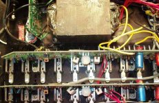
I may have a shot of an okay Carver. Yes, found it. This is a working M 1.5. I don't happen to have any in right now, but most look very close to this. What is not shown are the power supply board (along left side, front to back) and the input PCB where the XLR jacks would go (left side on rear panel close to the supply board).
-Chris
What, the Carver or Powerbase?
No pics of a Powerbase (Amcron or Crown in the USA). For the powerbase, imagine a chassis divided mid way to make two shelves. There is a fan placed in the middle (brilliant!). The bottom is dirt and some soot. The top half is a couple rows of transistors (no mica) and lots of carbon on the PC board. Blast marks too! Lots of fun. Replacing the boards is the best option is you really want to repair one. They blow for keeps.
I may have a shot of an okay Carver. Yes, found it. This is a working M 1.5. I don't happen to have any in right now, but most look very close to this. What is not shown are the power supply board (along left side, front to back) and the input PCB where the XLR jacks would go (left side on rear panel close to the supply board).
-Chris
Attachments
Hi imix500,
Wow, you get nailed on two ends then. You must see some beauty destruction come back. Innocent faces behind the burned gear. Or, likely there are some you just never see again.
Just do not rent for Caribana in Toronto - ever! Not that you would.
-Chris
Edit:
How are the amps for service? Do they lose many components or is the damage very limited as in a Carver?
Wow, you get nailed on two ends then. You must see some beauty destruction come back. Innocent faces behind the burned gear. Or, likely there are some you just never see again.
Just do not rent for Caribana in Toronto - ever! Not that you would.
-Chris
Edit:
I imagine you recone them. Still a pain (labour) and some cost. It's not as bad as an entire driver, motor, frame and all.the repair bill adds up quickly with this brand. Hence the deposit.
How are the amps for service? Do they lose many components or is the damage very limited as in a Carver?
- Home
- General Interest
- Everything Else
- Carver Magnetic Field Power Amp -whazzit????