Maybe another stupid question . But I think some of us use IR-remote control to control our diy audio equipment , I certainly do.
I'm making IR remote control with HT12 D & E . I can source these easily in country.
But only the enocoder HT12 E , not A version that has a 38Khz output to drive IR led's. No problem , I just add a 38Khz oscillator and gate it with the positive data output. It works , but the RC oscillator frequency is strongly related to the supply voltage.
With 2 AAA's that is 3.2 V to 2.2 V near empty. So the RC oscillator is just not posible.
Only way I see is like in most RC's : 455Khz resonator + divided by 12 , which is a bother an too many more components (counters/gates).
OR a 38Khz QXtal , like Mouser has (38.4 Khz ) paired with a AHC1G or even an AUP1G nand or nor gate.
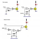
First version in pic , works with RC oscillator , it gets switched on and off with EVERY bit of the 3khz data output data , just not doable with a QXtal.
Second version in pic , the oscillator starts when pressing a button on the remote and only as long as the button is pressed . The AND gate modulates the 3Khz data output with the 38,4 Khz from the QXtal.
Here's my question :
Is a quartz crystal ok for this often on/off switching ? Will it shorten it's life ?
A RC oscillator has of course no problem with it , but a QXtal is different.
And : A RC oscillator like here with SchmittTrigger gate , starts immediately , first period is slightly longer . How quickly does a quartz ocsillator start ? Is there a a short time that the frequency isn't right yet ? In that case I need to start the transmission a little later from when the button is pushed.
I have no oscilloscope , so I can't check for myself.
Thanks !
I'm making IR remote control with HT12 D & E . I can source these easily in country.
But only the enocoder HT12 E , not A version that has a 38Khz output to drive IR led's. No problem , I just add a 38Khz oscillator and gate it with the positive data output. It works , but the RC oscillator frequency is strongly related to the supply voltage.
With 2 AAA's that is 3.2 V to 2.2 V near empty. So the RC oscillator is just not posible.
Only way I see is like in most RC's : 455Khz resonator + divided by 12 , which is a bother an too many more components (counters/gates).
OR a 38Khz QXtal , like Mouser has (38.4 Khz ) paired with a AHC1G or even an AUP1G nand or nor gate.
First version in pic , works with RC oscillator , it gets switched on and off with EVERY bit of the 3khz data output data , just not doable with a QXtal.
Second version in pic , the oscillator starts when pressing a button on the remote and only as long as the button is pressed . The AND gate modulates the 3Khz data output with the 38,4 Khz from the QXtal.
Here's my question :
Is a quartz crystal ok for this often on/off switching ? Will it shorten it's life ?
A RC oscillator has of course no problem with it , but a QXtal is different.
And : A RC oscillator like here with SchmittTrigger gate , starts immediately , first period is slightly longer . How quickly does a quartz ocsillator start ? Is there a a short time that the frequency isn't right yet ? In that case I need to start the transmission a little later from when the button is pushed.
I have no oscilloscope , so I can't check for myself.
Thanks !
Attachments
>Is a quartz crystal ok for this often on/off switching ? Will it shorten it's life ?
No, absolutely not
>How quickly does a quartz ocsillator start ?
Very slowly, especially if the base frequency is low (38kHz is) and the excess gain is kept reasonable, to avoid the degeneration into a vulgar multivibrator.
The oscillations build up slowly, in an exponential manner. The frequency will always be spot on, but the amplitude will make the signal unusable for most of the startup period.
Have you considered a LC oscillator? If you replace your crystal with an inductor, you can have a good frequency stability (slightly worse than a ceramic resonator, but much better than a RC multivibrator).
The starting time is not zero, but it is much faster than for a crystal.
As a starting point, I suggest a 1mH inductor and two 33nF capacitors, preferably reasonably good ones: polycarbonate, polypropylene or polystyrene.
The frequency should end being slightly too high, but you can arrive at the correct value by adding a small padding cap across one of the 33nF.
To experiment, you can use regular mylar caps, but for the final build use more stable types.
The resistor can be zero to start with (or a low value like 470 ohm).
You can then increase it until the oscillations become too weak for a reliable operation.
Opt for a value 30% smaller, to ensure a good stability and reliabilty.
The inductor can be a common resistor-like type, but if you find a better one, with an adjustable core, you will be able to tune the frequency very accurately
As an order of magnitude estimate, crystal oscillators that are specifically optimized for fast start up usually start in about 2000 to 10 000 times the period time (for fundamental mode crystals anyway, overtone oscillators are slower). The frequency is a bit off until the amplitude has fully settled, but not so much that it would matter for your application (order of magnitude: 0.1 %). Switching it on and off frequently is no problem, in fact this is very often done in battery-powered equipment to save power.
The Intersil/Renesas ICL7555IPAZ costs $0.87, consumes 60 microamps, wakes up from a dead start and oscillates at the correct frequency after 2 cycles (53 microseconds), works all the way down to 2.0 volt supply, and has an oscillation period which is independent of the supply voltage. DigiKey link
Thanks for your reply guys. As I feared the switching off and on of QXtals is not recommended. Even with a delay of 2000 times the period time ( MarcelvdG) that's about 50 ms , maybe doable , 10.000 times is a 260 ms , which is too much.
I thought about an LDO to keep the supply steady , but reasonably priced and available ones , draw 30-50 uA . Depending on the type , an AAA battery has 500 to 1000 mAh at 50 uA , that's 10 to 20.000 hours or 400 to 800 days standby time.
I think I can make a 38 kHz quartz oscillator for about the same 30-50 uA with an AHC or AUP gate and then no need for an extra LDO, and just keep the oscillator always on. Not the best solution. The little (obsolete ? ) jewel HT12E keeps it below 1 uA. + a little for the priority encoder 74HC148 to go from 16 to 4 data inputs.
Since Philips stopped their SAA30xx , not much choice in IR remote control chips.
A LC oscillator Elvee ? Are they not influenced by the supply voltage ? I'm not really a fan of inductors , unless used in buck/boost converters.
Same for one of the CMOS versions of the NE555 , the ICL7555 (Mark Johnson) , is this one really independent of the supply voltage ? It is a RC type too , so I don't think so.
Or maybe reconsider ceramic resonators. The HT12A works with a 455 kHz one , like in Elektors IR remote from frebruari 2000 (pg 22). It says : Any data input going low will wake up the encoder chip (HT12A) , start the 455Khz oscillator and the encoded datastream will be output from pin 17 (Dout)...
So 455 kHz ceramic resonators are fast starters ? Even if they take 10000 cycles , that's about 2 ms , of course adding a 12 divider.
Mouser has only one : https://www.mouser.com/ProductDetail/ECS/ZTB455E?qs=oGPfoFmS6kTiN0iXTHPCUg==
Or going higher frequencies : a MHz QXtal with an easier divider than 12.
Ah , choices !
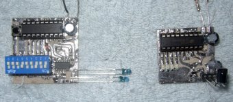
A pic of the 2 little test PCB's .
I thought about an LDO to keep the supply steady , but reasonably priced and available ones , draw 30-50 uA . Depending on the type , an AAA battery has 500 to 1000 mAh at 50 uA , that's 10 to 20.000 hours or 400 to 800 days standby time.
I think I can make a 38 kHz quartz oscillator for about the same 30-50 uA with an AHC or AUP gate and then no need for an extra LDO, and just keep the oscillator always on. Not the best solution. The little (obsolete ? ) jewel HT12E keeps it below 1 uA. + a little for the priority encoder 74HC148 to go from 16 to 4 data inputs.
Since Philips stopped their SAA30xx , not much choice in IR remote control chips.
A LC oscillator Elvee ? Are they not influenced by the supply voltage ? I'm not really a fan of inductors , unless used in buck/boost converters.
Same for one of the CMOS versions of the NE555 , the ICL7555 (Mark Johnson) , is this one really independent of the supply voltage ? It is a RC type too , so I don't think so.
Or maybe reconsider ceramic resonators. The HT12A works with a 455 kHz one , like in Elektors IR remote from frebruari 2000 (pg 22). It says : Any data input going low will wake up the encoder chip (HT12A) , start the 455Khz oscillator and the encoded datastream will be output from pin 17 (Dout)...
So 455 kHz ceramic resonators are fast starters ? Even if they take 10000 cycles , that's about 2 ms , of course adding a 12 divider.
Mouser has only one : https://www.mouser.com/ProductDetail/ECS/ZTB455E?qs=oGPfoFmS6kTiN0iXTHPCUg==
Or going higher frequencies : a MHz QXtal with an easier divider than 12.
Ah , choices !
A pic of the 2 little test PCB's .
Attachments
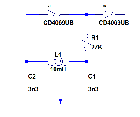
I made a quick test of the LC solution. This is the circuit I tested:
This is the real-world version:
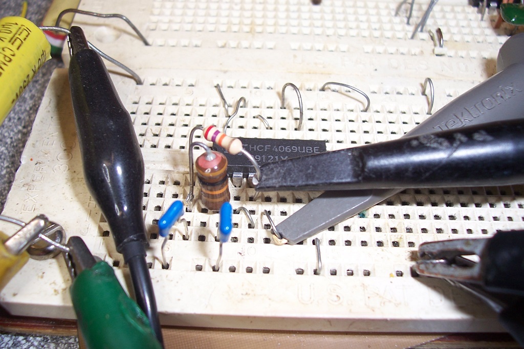
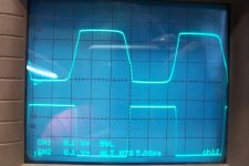
These are the output waveforms. On top, the direct oscillator output, bottom after the buffer gate:

With the components used, the oscillation frequency is 38.3kHz. The caps are ceramic COG.
To arrive at exactly 38.4kHz, it would be prudent to make one of the caps 2.7nF and add a suitable adjustment cap of 470pF or 560pF, depending on the exact values.
The current consumption is 15.5µA, and the oscillator starts at 2.5V; once started, it operates down to 2V.
The frequency variation between 2.5V and 3V is ~15Hz
This is the real-world version:
These are the output waveforms. On top, the direct oscillator output, bottom after the buffer gate:
With the components used, the oscillation frequency is 38.3kHz. The caps are ceramic COG.
To arrive at exactly 38.4kHz, it would be prudent to make one of the caps 2.7nF and add a suitable adjustment cap of 470pF or 560pF, depending on the exact values.
The current consumption is 15.5µA, and the oscillator starts at 2.5V; once started, it operates down to 2V.
The frequency variation between 2.5V and 3V is ~15Hz
Attachments


Ceramic resonator oscillators can indeed start much faster than crystal oscillators, even at the same frequency. Ceramic resonators have a much smaller ratio between the static electrode capacitance and motional capacitance than quartz crystals. When you do all the math, you find that that translates into less cycles needed for start-up.
What is the bandwidth of your receiver? That will determine how accurate your frequency needs to be.
What is the bandwidth of your receiver? That will determine how accurate your frequency needs to be.
I have made my own IR transmitter using an Atmel attiny mcu, a small keyboard etc of course you have to write the code
Imo using a mcu is the most universal way to do it. In many cases the problem lies in determining the protocol of the IR signal required and the codes, address/command that are required to make the receiver respond.
Imo using a mcu is the most universal way to do it. In many cases the problem lies in determining the protocol of the IR signal required and the codes, address/command that are required to make the receiver respond.
I'm using Vishay TSOP38238 . Looking at the graph on the data sheet , anything between 37 and 39 kHz would be better than 0,8 (80 %) of the maximum at 38 kHz.
Yes I have 32,768 kHz , but that is way to low , not sure what you mean by : 2 E 15 IIRC so you can divide by 2 ... NareshBrd.
Ceramic resonator of 455 khz or more could do , but then again so can quartz like 1,22 MHz divided by 32 or 2,45 MHz div 64 , Mouser has them , not cheap , even at 20.000 cycles startup that is better than 2 ms or less.
The LC option is remarkable , Elvee . Especially because 4069UB has a minimal voltage of 3 V.
But I've written in another thread that it can go below 3 V as a quartz osillator.
Will it work with buffered HC , AHC or even an AUP gate ? (in stead of the unbuffered )
How come it stays at the same frequency when supply goes from 3 to 2,5 V ?
How about from 3,2 to 2 V ? Yes I know the TSOP and HT12 supposed to have at least 2,5-2,4 V, but I'm sure they will work at 2,2 V (1,1 V x2 of near depleted AAA batteries).
15,5 uA is in the range to let it oscillate all the time , not just when you press a button.
Atmel attiny mcu ... yes that is what folks do these days, rsavas. I'm old school , no mcu or other processors (that's over my head) , just logic and dedicated IC's like HT12 .
All 555s oscillate at a frequency independent of the supply voltage. They achieve this result by using 2 resistors and one capacitor, and by cleverly arranging the switching threshold points so the voltage-versus-time expression takes the form
Voila, the Vcc terms cancel out and the result is independent of Vcc. That's why 555's took over the (multivibrator IC) world, 45 years ago: because their timing behavior is set by external, precise, components and not by the supply voltage.
However, if 60 uA consumption is unacceptably high, I recommend you design a free running, always-on, discrete component crystal oscillator that consumes, say, 3 uA, plus an output enable gate that swings rail to rail for whatever the supply voltage happens to be at the moment (while the battery discharges). The enable gate will probably consume another 3 uA. Remember: if the wristwatch guys can make a low current crystal oscillator that's always on, so can you!
You can source discrete NMOS transistors with suitably low threshold voltages, but low-Vt PMOS discretes will be a lot harder to locate.
_
- [Const1 * Vcc * exp(-t / Rthev*C)] / [Const2 * Vcc]
Voila, the Vcc terms cancel out and the result is independent of Vcc. That's why 555's took over the (multivibrator IC) world, 45 years ago: because their timing behavior is set by external, precise, components and not by the supply voltage.
However, if 60 uA consumption is unacceptably high, I recommend you design a free running, always-on, discrete component crystal oscillator that consumes, say, 3 uA, plus an output enable gate that swings rail to rail for whatever the supply voltage happens to be at the moment (while the battery discharges). The enable gate will probably consume another 3 uA. Remember: if the wristwatch guys can make a low current crystal oscillator that's always on, so can you!
You can source discrete NMOS transistors with suitably low threshold voltages, but low-Vt PMOS discretes will be a lot harder to locate.
_
Last edited:
Old school or not you still have to address the issues I mentioned above.
If you ever want to learn using a mcu, I have a book and code ( written in bascom) that builds a simple IR receiver which can display the protocol, address, command
Bascom is a low cost basic compiler for the atmel avr series mcu
It is fun to learn this stuff
A digital scope helps a lot but they do not decode the signals, that is the fun part.
A mcu sleeps drawing uA until it senses a key press which triggers an interrupt to wake the device up to scan the keyboard
Last edited:
It is not within the recommended operating conditions, and your mileage may vary depending on the source of the 4069.The LC option is remarkable , Elvee . Especially because 4069UB has a minimal voltage of 3 V.
But I've written in another thread that it can go below 3 V as a quartz osillator.
The one I tested is from ST.
The gain of CMOS gates tends to increase with decreasing supply voltage, until the threshold voltage cannot be reached.
The sweet spot for regular Aluminum-gate CMOS is around 3V
HCU types will certainly work, normally better than a regular CMOS, and I can make the test for you since I just need to find a 74HCU04 and plug it into the breadboard.Will it work with buffered HC , AHC or even an AUP gate ? (in stead of the unbuffered )
If I have one left in my drawers, I'll let you know tomorrow.
A-types and other more modern CMOS families are trickier, because they either include a Schmitt-trigger input, or are buffered or have an asymetrical output stage (and sometimes all three of them).
Oscillate they will, but how clean or accurate will it be?
I can make the test too: I certainly have some 74AC04 in my stock, maybe some 74ABT04. I certainly have a 74HC04, but I am not too optimistic
The frequency is defined mostly by the tank circuit: the resonance of the inductor with the two capacitors which can be calculated with the Thomson formula: F=1/6.28*√(L*C), C being the equivalent series value of the two caps.How come it stays at the same frequency when supply goes from 3 to 2,5 V ?
How about from 3,2 to 2 V ?
The supply voltage or the characteristics of the gate do not appear in the formula, meaning they have a minimal influence.
The Vdd will slightly affect the frequency, as observed, because the pseudo-period of the tank circuit slightly depends on the damping (thus gain) of the circuit surrounding it, and the saturation effects.
The capacitances of the semiconductors also vary with the voltage, meaning the frequency tends to increase (slightly) with an increasing supply.
A crystal oscillator displays the same kind of effect, but much reduced thanks to the very high Q-factor. The high Q also means a long startup time.
A ceramic resonator is somewhere in-between
A 74HCU04 will normally work at supply voltages well below 2V, but it will consume more current.Yes I know the TSOP and HT12 supposed to have at least 2,5-2,4 V, but I'm sure they will work at 2,2 V (1,1 V x2 of near depleted AAA batteries).
15,5 uA is in the range to let it oscillate all the time , not just when you press a button.
If I have the possibility, I'll make the test and let you know.
Note that a LC can be used with a divider: a CD4060 for example.
You could use a small AM-IF 455kHz transformer to oscillate at 307kHz with two small additional caps and use the divide by 8 output to get your 38kHz.
Or any other combination....
A LC oscillator is just like a quartz or a resonator, except it is less stable but adjustable at will
Last edited:
All 555s oscillate at a frequency independent of the supply voltage. They achieve this result by using 2 resistors and one capacitor, and by cleverly arranging the switching threshold points so the voltage-versus-time expression takes the form
Voila, the Vcc terms cancel out and the result is independent of Vcc. That's why 555's took over the (multivibrator IC) world, 45 years ago: because their timing behavior is set by external, precise, components and not by the supply voltage.
- [Const1 * Vcc * exp(-t / Rthev*C)] / [Const2 * Vcc]
However, if 60 uA consumption is unacceptably high, I recommend you design a free running, always-on, discrete component crystal oscillator that consumes, say, 3 uA, plus an output enable gate that swings rail to rail for whatever the supply voltage happens to be at the moment (while the battery discharges). The enable gate will probably consume another 3 uA. Remember: if the wristwatch guys can make a low current crystal oscillator that's always on, so can you!
You can source discrete NMOS transistors with suitably low threshold voltages, but low-Vt PMOS discretes will be a lot harder to locate.
_
Didn't know that about the 555 types. 30 years ago I used them but took a liking to
others like the 4047 , the great VCO in 4046 ( I had to buy them in a tube of 25 ,
so I had more than enough to waste on using only the VCO) and of course the
Schmitt trigger gates 4093 , 40106 , HC132 , HC14.
If I wanted a rock solid freq , I use quartz.
Designing a discrete component crystal oscillator that consumes less than 5uA (for 32 to 38kHz) is beyond me. I hoped a 74AUP with a 4pF Cpd (or a 74AHC) at a low voltage could do the same or at least in the tens of uA range.
Bascom is a low cost basic compiler for the atmel avr series mcu
It is fun to learn this stuff
It is fun to learn this stuff ... I guess that is a matter of opinion. Too old to learn .
2 E15 meant 2 to the power 15, like 2 squared is 4, 2 cubed (3) is 8, and so on.
Clocks and watches use a 15 stage divider (by 2 each stage) to get the one second measurement they need.
Maybe you could use that chip at 38 kHz input...
I know how clocks work. I made a 10 MHz freq reference (an idea from Elektor) using a Casio wristwatch and a PLL (phase locked loop) . Too many components to get 38kHz from a 32.768 or its 2 to the 15 power divider.
Oscillate they will, but how clean or accurate will it be?
I have often read that the buffered CMOS is not good for quartz oscillators , but I have used them anyway. I recently made a 20MHz one with 74LVC00 , and it works , but a 74AHC1GU04 is on my list to buy. I like these 1 gate tiny IC's.
The LC circuit is definitely worth a try , I have 1nF NPO's in SMD but not the 1mH. Still the rock solidness of quartz or a ceramic resonator , with nothing to tune is appealing.
Btw : you first write 1mH with 33nF , then the pic says 10mH with 3,3 nF. Is this right ?
And a side note : your design of the inrush current limiter is next . I finally got the HV mosfets and the 5 W R's and will start to test it with lower powered switchers like phone chargers and broken external harddrive supplies. Not looking forward to testing and measuring with the mains electricity on.
With Elvee testing LC oscillator with 4069UB , I searched my notes again from when I tested it with 32.768 kHz at 3 V , and it was around 10 uA (measured over a 1 ohm resistor , so approximately 10uA with 2 of his buddies buffering its output) , which is close to Elvee's LC with 15,5 uA or even a wristwatch on a Li battery drawing a couple of uA.
I was focussed on an on/off oscillator so it needed to be a NAND or NOR gate to switch , not an inverter. Stopping an inverter oscillator can only be done by cutting the power via a P-mosfet or shorting its input to the + or ground . Collector/emitter or drain/source capacitance would influence the frequency. 4069UB only reliable from 3 V and only using 1 or 2 of the 6 inverters is not great , same for the 74HCU04 . So I think the 1GU , like AHC1GU04 or AUP1GU04 always on quartz oscillator may be the way to go.
I was focussed on an on/off oscillator so it needed to be a NAND or NOR gate to switch , not an inverter. Stopping an inverter oscillator can only be done by cutting the power via a P-mosfet or shorting its input to the + or ground . Collector/emitter or drain/source capacitance would influence the frequency. 4069UB only reliable from 3 V and only using 1 or 2 of the 6 inverters is not great , same for the 74HCU04 . So I think the 1GU , like AHC1GU04 or AUP1GU04 always on quartz oscillator may be the way to go.
Yes: what counts is mainly the L*C product.Btw : you first write 1mH with 33nF , then the pic says 10mH with 3,3 nF. Is this right ?
Thus, the pairs of values are equivalent in theory, but I opted for a 10:1 ratio after making a quick mental calculation: the L/C ratio needs to be suited to the active device used, and the final values I adopted look better suited to CMOS gates. I didn't test the initial values, but I can do it if you find them more convenient.
I have now tested other logic families, and they worked better than I expected.
First, a 74HCU04; I expected it to work, and it did: it starts at 1V and varies less than 10Hz between 2.5V and 3V.
At 3V, the supply current is a substantial 696µA, which came as no surprise.
Then, a 74AC04. Initially, I thought it had issues: the base frequency was correct, but the edges were very noisy; it could have been cleaned up with a small RC, but I realized that a breadboard with a distant bypass cap was not ideal for such a fast beast, and I plugged a 100nF ceramic directly along with the supply pins, and it tamed it completely: the waveform was an ideal square, no need to take a picture, it looks exactly like the waveform from a simulator (without the buffer gate).
It starts at 1.5V, and consumes 258µA at 3V. Also less than 10Hz variation.
Finally, a 74HC04: with a good bypass, it also worked well, started at 1.2V, consumed 143µA at 3V, had a clean square out without buffer and varied less than 10Hz.
All of them oscillated at 38.5kHz, because they are faster and have lower capacitances than legacy CMOS.
I didn't test other families, because converting them from SMD to DIP for a one-off breadboard test was too much of hassle for me. Sorry Rick, but I think you now have a good range of promising candidates already if you opt for the LC solution.
Since the buffered/special gates seem to work well, you can probably use a NOR/NAND/XOR gate for gating.
If you want to stay with plain inverters, low power gating can also be achieved with a diode, high value R and C combo.
We will see what the real-life test yields. This was sim-only testedAnd a side note : your design of the inrush current limiter is next . I finally got the HV mosfets and the 5 W R's and will start to test it with lower powered switchers like phone chargers and broken external harddrive supplies. Not looking forward to testing and measuring with the mains electricity on.
- Home
- General Interest
- Everything Else
- Frequent on/off switching of quartz crystal oscillator