Hello folks, I want to build an audio power amplifier, but not for music use. The objective is to build an AC power supply.
A signal generator that can output between 40 Hz and 400 Hz will drive this amplifier, which will output up to 250 Vrms. The output will be feedback controlled to the adjusted voltage level. As you might guess, distortion and other audio quality metrics are not important. Stable voltage output, good regulation, and sustained maximum power output is important. Initially I want to achieve 1 kVA power, but with the option to increase this as needed.
I looked for circuits online, but the ones I find don't go as high voltage as I need. What kind of topology do I need to consider for this? Valve amps seem to be a nice fit for this purpose, but I neither have the experience with valves, nor can I source any valves here locally. Can you guys point to me to any relevant information on this subject? Maybe books written by the audio greats that touch on this subject so that I can buy that book?
I had an amplifier once with +/÷ 150 volt rails, so 300v peak to peak.
I believe it was a ecler pam 6100.
What load should it drive this amp of yours?
I can source amplifiers with about 100 Vrms output here, but then I need to attach a transformer after it, which I don't want to do.
Target output power is 1 kVA. The type of load is anything that can be plugged into the wall outlet. In other words, any combination of resistive, capacitive, and inductive loads.
You mean inverter? I'd rather go fully linear, because I want good output regulation, and an inverter will be too slow in responding to output voltage changes.
Also, getting the inverter work well for a wide range of voltages (0 - 250 Vrms) and between 40 - 400 Hz will be a challenge.
Using a linear amplifier also gives the option of manipulating the input signal any way I see fit (starting sine wave at a certain phage angle, adding noise and other disturbances to the output).
Sounds like what you want is a class D amplifier, operating at a fairly low switching frequency (a few kHz). This is essentially what modern solar inverters are. They can be made very efficient, and free from the cross-conduction problems associated with full-fidelity class D audio amps. It can still be made a “linear” amplifier rather than just fixed output, by using the same sort of error amp front end as a typical hi-if class D amp. I would start by studying inverter schematics for ideas.
A class AB power amplifier operating at these voltages will end up being a pain in the ***. Way too much heat - probably a lot of blown power transistors. 3 or 4 step class H might be practical. More straightforward to design than class D, more complicated to build.
A class AB power amplifier operating at these voltages will end up being a pain in the ***. Way too much heat - probably a lot of blown power transistors. 3 or 4 step class H might be practical. More straightforward to design than class D, more complicated to build.
Sounds like what you want is a class D amplifier, operating at a fairly low switching frequency (a few kHz)
Even though the maximum output frequency is 400 Hz, I think I'll still need a much higher bandwidth, because I want the ability to start and end the sine wave at an arbitrary phase angle and these steep rise and fall times require the extra bandwidth. If I can achieve 100 kHz bandwidth I will be happy, but otherwise I'll settle for whatever I can get.
I'll start looking into class D design. Actually, isn't an true sine output online UPS exactly that? I have thought online UPS for this, but I'm not sure whether it will go between 0 - 250 Vrms and between 40 - 400 Hz output, and whether it will have a high enough bandwidth for sine wave disturbances.
Just a thought, why go through all the steps of feeding it a sine wave and amplifying that, when you could just build a power oscillator?
Because of the flexibility of generating the sine wave using a DSP. I can add any disturbance to the sine wave I want, which will be very important for testing power supplies.
Use IGBT, there are designs for voltage controllers available...
Thanks for the response, will look into this.
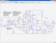
I have developed a number of HV amplifiers and opamps for various purposes.
This one is used in my Early-meter, and is tested and functional:
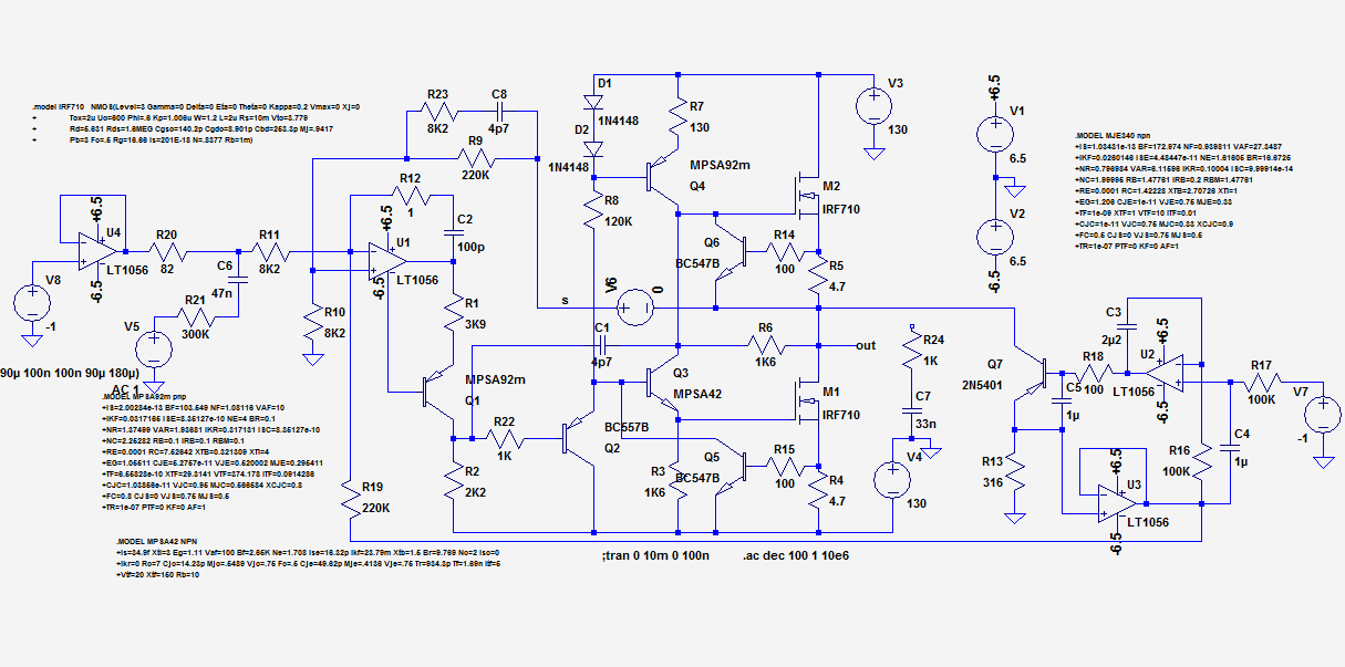
It uses supplies of only +/-130V, but the concept can be pushed to higher voltages.
Ignore the front section upstream of R11 and the output after (and including) Q7.
It is designed for 100mA max. output, but this can be upgraded too. It is protected with a current limiter.
The limiting factor would be the Vceo of the MPSA transistors.
You could still get a 325V peak output with +/-200V supplies and a H-bridge configuration.
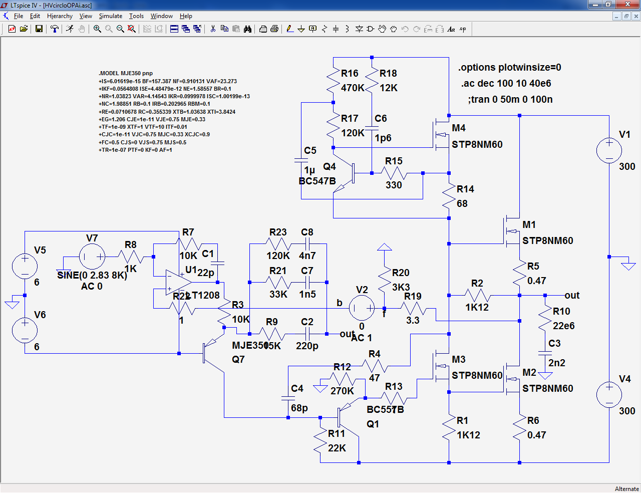
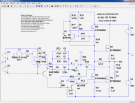
Alternatively, you could use NMOS transistors for the CCS and the VAS, as in these examples:
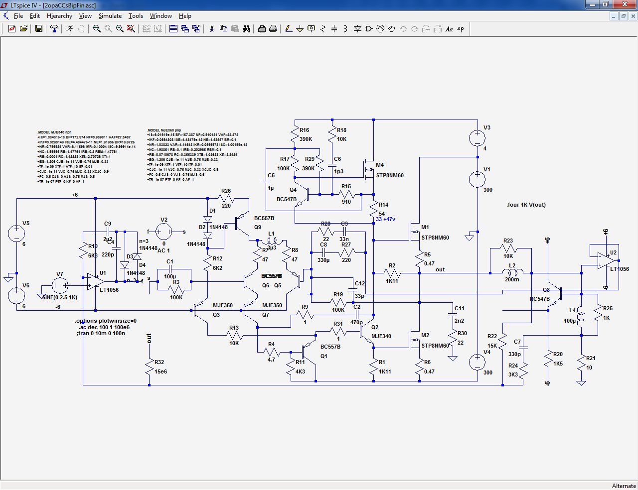
They have been designed for a transformer tester, but they have not been completely built and tested.
They should be workable though.
Q2 needs to have a 800V Vceo. I used the MJE340 in the sim because I had the model, but I didn't have the model of the 2SCxyz that should be used.
In the full MOS version, M3 and M4 can be low-power types.
These circuits are designed for 1A output, but they could be upgraded for higher currents.
It is possible to arrive at much higher voltages, see here for example:
Self-cascoding, a tool for creating ultra high voltage building blocks:
This one is used in my Early-meter, and is tested and functional:
It uses supplies of only +/-130V, but the concept can be pushed to higher voltages.
Ignore the front section upstream of R11 and the output after (and including) Q7.
It is designed for 100mA max. output, but this can be upgraded too. It is protected with a current limiter.
The limiting factor would be the Vceo of the MPSA transistors.
You could still get a 325V peak output with +/-200V supplies and a H-bridge configuration.
Alternatively, you could use NMOS transistors for the CCS and the VAS, as in these examples:
They have been designed for a transformer tester, but they have not been completely built and tested.
They should be workable though.
Q2 needs to have a 800V Vceo. I used the MJE340 in the sim because I had the model, but I didn't have the model of the 2SCxyz that should be used.
In the full MOS version, M3 and M4 can be low-power types.
These circuits are designed for 1A output, but they could be upgraded for higher currents.
It is possible to arrive at much higher voltages, see here for example:
Self-cascoding, a tool for creating ultra high voltage building blocks:
Attachments
A transformer is out of the question. Not because of noise, but because it will only pass clean sine waves unmodified. Anything else, and it will be mangled by the transformer. Also, there will be current limiting feature. If I detect over current and turn off amp, the transformer might still deliver enough energy to the load to kill it. Also, the presence of the transformer complicates the feedback loop. It will introduce funny non linearities which I don't know how to compensate for.
The most reliable way is oscillator and high bandwith amp. Any change to the input signal will arrive at the output almost instantatneously.
The most reliable way is oscillator and high bandwith amp. Any change to the input signal will arrive at the output almost instantatneously.
- Home
- General Interest
- Everything Else
- High voltage power amplifier