Here are some on banggood for about 50€
Well that’s an amazing value for money.
But starting at 50Khz misses the important audio range from 100Hz to 50Khz.
Hans
But starting at 50Khz misses the important audio range from 100Hz to 50Khz.
This is possible, but it costs extra. For example this analyzer uses some RF transformers, and these have limited bandwidth. There are probably other components that limit bandwidth. I spotted a few RF switches that are cheap because they're used for ubiquitous cellphone/wireless frequencies, but a quick datasheet check shows they stop at 100kHz on the way down. Also the mixer has a low frequency limit, etc.
So yeah if you add $$ for a few high quality RF switches, and more $$ for separate signal paths designed for each range of frequency, you can get a wider range... but that's not the point of this project...
A soundcard makes a nice LF network analyzer btw. I have a N2PK network analyzer, and I just stitch the graphs from it and the soundcard with some python scripts.
Last edited:
Maybe it’s a better idea to just measure the inductance and DC resistance with shorted cable and eventually the capacity with open ended cable.Here are some on banggood for about 50€
That will do.
Hans
")
Hans, I’ve measured this parameters on my speaker cable:
L= 4,54µH C=250pF R=0,23Ohm so SQRT(L/C) gives Z= 133Ohm (~4m in length)
My speakers are 6Ohm, so this is my target impedance, right?
So I need ~120nF to add to the cable, evenly spread over the length?
Thanks, Boris
L= 4,54µH C=250pF R=0,23Ohm so SQRT(L/C) gives Z= 133Ohm (~4m in length)
My speakers are 6Ohm, so this is my target impedance, right?
So I need ~120nF to add to the cable, evenly spread over the length?
Thanks, Boris
Hi Boris,
To be sure that we use the right figures:
The 0,23R you measured is for 4meter shorted at the end, so for 8 meter cable in total gives 29mR/meter.
That would mean that you are using a 0,7mm^2 zip cord, right ?
That's quite small for this exercise, but I will make the sim for you this afternoon and show you the result with this cable and with a thicker one.
Hans
Thanks, Hans. Yes the resistance is for 8m cable (4m/shorted at one end).
I have given up cable experiments in the past and I use this cable only because I was too lazy to look up for something better. But I find your results highly interesting and it encourages me to start experimenting again...
Boris
I have given up cable experiments in the past and I use this cable only because I was too lazy to look up for something better. But I find your results highly interesting and it encourages me to start experimenting again...
Boris
Boris,
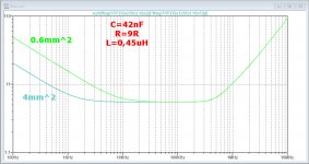
You mentioned to have 6R speakers, that's why I have optimised the cable for 6R.
I have simulated Zo for your 0.6mm^2 cable and for a 4mm^2.
Quite obvious is the big difference at LF.
I have assumed to divide the cable in 4 equal parts, and to connect at the 3 points in between resp 42nF, 0.45uH and 9R, all components three in series.
The 9R should be a very low inductance 30Watt (current sense) resistor and the 0.45uH should be a version for several amps.
Hans
.
Attachments
Last edited:
Hi Boris,
Dividing the cable in 4 equal section, at the 3 points intermediate points, you will need to connect in series at each point between the two conductors:
0.45nH >5 Amp
8R >20Watt low inductance
35nF polypropylene >40Volt AC
This will give you a cable with Zo=6R in the audio range.
Anxious to hear what this will bring to your sound perception.
Hans
- Home
- General Interest
- Everything Else
- Zip cord for speaker test