Here is a first attempt at IMD. I had to dig out an old M-Audio Fast-Track USB card because the IMD of my Behringer card is so high - typical Behringer analog circuit. 
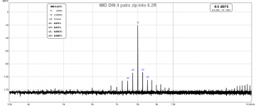
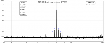
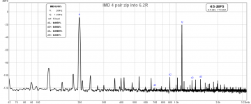
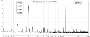
Here you'll see the IMD of both DIN and a custom frequencies played thru the 4 pairs of zip wired and into a 6.2R resistor and into the Bowers & Wilkins HTM62 speaker. The Amplifier is a Yamaha V-2700 receiver in bypass mode. Please let me know if this is what you're looking for.
Here you'll see the IMD of both DIN and a custom frequencies played thru the 4 pairs of zip wired and into a 6.2R resistor and into the Bowers & Wilkins HTM62 speaker. The Amplifier is a Yamaha V-2700 receiver in bypass mode. Please let me know if this is what you're looking for.
Attachments
I couldn't find the crossover freq for that speaker, do you know what it is? To have any effect on IMD, the two frequencies have to go into the same driver.
What is being used to measure the IMD, the speaker doesn't seem to have any IMD beyond a pure resistor.
Its billed as a center speaker, so I assume you only have one..
Do you have two of the fullrange speakers to use for image stability?
jn
What is being used to measure the IMD, the speaker doesn't seem to have any IMD beyond a pure resistor.
Its billed as a center speaker, so I assume you only have one..
Do you have two of the fullrange speakers to use for image stability?
jn
I assume that the crossover is at the ~2.2K impedance peak. That's typical of slightly underlapped filters.
I do have two of the fullrange and also two of the small B&W that go with the center speaker.
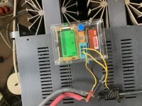
For measurement I am using an USB audio card. It is the M-Audio Fast Track. I also have a Fast Track Pro if I can find it. RCA line level out of the card into the Yamaha left channel. Thru the 4 zips to the speaker. The picked up into the 1/4" line input of the M-Audio.
I do have two of the fullrange and also two of the small B&W that go with the center speaker.
For measurement I am using an USB audio card. It is the M-Audio Fast Track. I also have a Fast Track Pro if I can find it. RCA line level out of the card into the Yamaha left channel. Thru the 4 zips to the speaker. The picked up into the 1/4" line input of the M-Audio.
Interesting, it isn't picking up any IMD from the speaker...
Do you know if the input to the analyzer is isolated, as in a differential input, or is ground complicating things.
Well, that will be a question for another day. I was thinking it might pay for me to make a zero inductance 50 or 100 milliohm resistor that could be put at the speaker, and perhaps someone here could design up a simple differential preamp to see the current at the speaker...with my mill, it's trivial to put a few hundred holes in a pair of brass plates to solder a hundred resistors in to make a zero magfield resistor.
My thinking is that because the zip Z is higher than the load, the settling time is due to the line being charge to full current by reflection transits, so measurement of of the current may be a better tell, and speakers are current driven devices.
Connect both fullrange to one amp channel, then do the IMD check on one speaker first as a baseline with the zips not split just to make sure nothing weird happens with the amp and 8 parallelled zips.
Before splitting the one set of 4 zips, see if the image is totally stable. The speakers can be close together or not, and just listen in the sweet spot to confirm both drivers are audibly identical. Then split one 4 pair into bundled positives and bundled negatives, re-listen in the sweet spot to see if any of the image changed, drifted, or smeared.
Then use the IMD test on the speaker with rebundled conductors.
Then re-do the center channel speaker IMD to see if it changed..
You had mentioned somewhere you are time limited, so iterations on the test setup may have to wait, which would work with me as well. Drilling hundreds of holes into 3 pieces of .062 inch brass might take a few drill bits.. I wonder if I can convince my baby cnc to drill holes.
jn
ps..I should draw up a diagram of what tests we're talking about so there is no confusion between us...and again, thank you for the efforts.
This maybe an article of interest - Cable Impedance at audio frequencies
"Matching cable impedance to load impedance is sometimes advised, and here the effects of reflections from an unmatched load are investigated"
"Matching cable impedance to load impedance is sometimes advised, and here the effects of reflections from an unmatched load are investigated"
^ Thanks for the link.
JN -
JN -
- The line input currently used is not differential, let me see what I can do about that.
- Yes, there is a time crunch for me, Thursday will be my last chance for awhile. The listening stability test might have to wait.
- Drawings of what you want would help us to be sure the test is what you have in mind.
- It's quite possible that I can do some of this testing over the summer. I'll carry the necessary gear with me.
Thank you for the link. it is a reasonably good explanation. Me, I would have added in a lot of acronyms in a blatant attempt at looking smart..This maybe an article of interest - Cable Impedance at audio frequencies
"Matching cable impedance to load impedance is sometimes advised, and here the effects of reflections from an unmatched load are investigated"
I glossed through it quickly before my first cup of coffee, but did see something off the mark. In his spice sim of a 100 ohm cable 3 meters long, he uses 10 nSec as the transit time, which is ~speed of light. The only cables that are capable of that kind of speed are the air dielectric coax cables, (heliax for example), and foam dielectric cables (times microwave LMR250 if memory serves me correctly) and a few Belden foamed PE cables. The crux is, the relative dielectric coefficient has to be very close to 1, as the prop velocity is related to 1/sqr(epsilon). For a coax, a plastic of coefficient 4 (which is quite typical for plastics) will have a prop velocity of .5. But that is only for coax, which is a constrained system.
Note: the true eq is Vc/sqr(epsilon times mu), but there are very few times where the desire is to increase the dielectric's permeability, as that increases the impedance. RCA female jacks a notable exception, but why bother?
A zip cable is an example of an unconstrained cable. IOW, the magnetic field is NOT constrained to remain within the volume of the dielectric, but instead splays out into free space as a dipole field. The result is more reduction of the prop velocity.
This can be expressed as Vc/sqr(LC), Vc being light speed. As the product LC increases, the prop velocity gets slower. Typical values for speaker cables reduce the prop velocity to numbers closer to .2C.
All constrained cables follow the equation LC=1034*DC, L in nH per foot, C in pF per foot. DC is just the dielectric constant of the insulation.
All unconstrained cables follow the equation LC=1034*EDC. Effective dielectric Constant takes the splashing inductance into account, but is not easy to calculate. Rather, measure a cable inductance and capacitance, then calculate the EDC. Prop velocity will be Vc/sqr(EDC).
In the experiment we are running, the splitting of the four conductors will cause the cable impedance to climb out into the 500 ohm plus range, so the equivalent prop velocity will be well below .1, transit times out into the 100 to 200 nSec range. The charging delay with a 5 ohm load will be gross for the split conductor, while at the same time it will be zero for the 4 pair unsplit zip.
If this cannot be heard in the two speaker one amp channel test even at this gross a level, move on, taint nuttin to see.
Pano, try the split test before thursday, then call it a day. As you can see, my excel graph was from 2014, so there is no real hurry. The stuff will be here when you get back. If you are vacationing, don't carry this garbage with you, relax and enjoy as life is too short.
Again thank you.
jn
Last edited:
Just for the record,
Because I promised to do a test with different cables connected to one amp driving in this case two ESL63 speakers, that's what I just just did with two different cables, both having the same length of 3 meter.
One zip cable with 2*1.5mm^2 having 986pF and the other one being my standard speaker cables with 134nF each.
Probably some will declare me to be mad, but I heard a big difference, although at my age the last thing I want to claim is to have golden ears.
I listened to Fields of Gold performed by Eva Cassidy because of exceptional good articulation and recording quality.
In both case the sound came exactly from the middle.
With the same cables sound was spacious and involving, but with two different cables the space was gone and the image became much narrower and flat.
So all cables sound the same ? Not for me according to my very subjective experience.
And just for Evenharmonics, yes I had my eyes wide open from surprise.
I could have tried a third official LS cable having almost zero capacity, but since the difference was already so obvious with the other two, I called it a day.
Hans
Thanks Hans for that. Did I read it right that one cable is over 100nF? That seems very high to me, is it?
JN, not vacation; work. Audio work where I will have real problems like 100s of feet of old speaker cable, some of it buried, some in air. 26 speakers that stay out in the rain for months at a time, another dozen under shelter but still exposed. An amp room that floods from time to time blowing out amplifiers and such. Lightening strikes and worst of all, 33 actors with wireless microphones!
It's work, but I love it. The setting is ideal.
Attachments
Given that reports or claims of speaker cable effects may be described by humans in perceptual terms, say, changes to location, width, depth, etc., one might wonder what would be most useful to measure? Measuring one channel at a time for changes may not be as fruitful as measuring for differences between channels?
Last edited:
Ah, but it is not measuring one channel for differences.
It is using one amp source in order to control the source.
If two amp channels are used, there will be a question of "does the cable with high capacitance" cause a problem with it's channel?
It's all about controlling as many variables as possible. Identical speakers (checked as it were by imaging a monophonic pair), same length cables, same resistance cables (4 conductors at each terminal).
The only thing being evaluated is the RFZ of the cable affecting the imaging.
With speakers it is probably not going to go so well trying to use electronic means to measure as room reflections will certainly mess it all up.
I think the IMD test is probably the most applicable test, but the levels and frequencies which can bring out any cable difference at the speaker is currently an unknown. Levels, I would want good excursion to bring out flux dragging modulation, but that makes it hard to be in the room.
This is however, a nice collaboration effort.
jn
Understand the present goal is to test a particular hypothesis.
Guess my interest would be more along the lines of trying to gain some insight into what technical differences between channels correlate with human verbal descriptions of perceptual changes in the stereo illusion?
Guess my interest would be more along the lines of trying to gain some insight into what technical differences between channels correlate with human verbal descriptions of perceptual changes in the stereo illusion?
Last edited:
I am also interested in that as well. His descriptors caught me off guard, making me think long and hard. However, reduction of which variables are changed is a good first step towards test repeatability, and hopefully provides some insight as to how to test.
Went down that rabbit hole many years ago tracking down an imaging problem I had with a very early on sound card that had one DAC and used two S/H circuits to get left/right. The interchannel delay messed the image up, as the LF content was centered since humans can't use LF ITD to process image shift.. But much of the content was shifted off center, and no effort with the pan control could give me a proper image. And how my brain processed the sound was weird. It was like the image wanted to lock in direction, fighting the pan pot.
jn
Last edited:
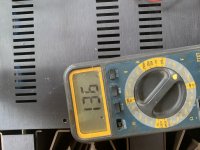
I can only agree that 100nF seems insane, so I could measure the cable impedance with resp. open ended and shorted from 100Hz to 10Mhz.
I measured the capacity in two different ways giving the same result.
Hans
P.s. will also measure the impulse response on both sides of the cable.
I measured the capacity in two different ways giving the same result.
Hans
P.s. will also measure the impulse response on both sides of the cable.
Attachments
Last edited:
Went down that rabbit hole many years ago tracking down an imaging problem I had with a very early on sound card that had one DAC and used two S/H circuits to get left/right. The interchannel delay messed the image up, as the LF content was centered since humans can't use LF ITD to process image shift.. But much of the content was shifted off center, and no effort with the pan control could give me a proper image. And how my brain processed the sound was weird. It was like the image wanted to lock in direction, fighting the pan pot.
For whatever it's worth, in all seriousness, if you haven't looked at some of the vector math etc. and attendant work that was done for quadraphonics, specifically the matrix systems, you might want to take a gander since they were inherently dealing with channel separation, phasing & image perception, and there was some very interesting work done that got largely forgotten when the whole sorry mess collapsed. SQ was probably the pick of the matrix systems in terms of encoding, for all its issues, although the baseline RM and similar QS were interesting in their own rights.
- Home
- General Interest
- Everything Else
- Zip cord for speaker test