I found this article interesting as it shows measurement to try to explain the differences in speaker cables.
The “Sound” of Speaker Cables: an Analysis | PS Audio
The “Sound” of Speaker Cables: an Analysis | PS Audio
An interesting read indeed, Rick, but worth bearing in mind that the researcher and author just happens to manufacture the 'best sounding' cable. Call me an old cynic if you will - perhaps I should just let the measurements speak for themselves!
")
Personally, short and thick is good enough for me - and that's not intended as a comment on my stature and mental ability!The results show that the principal factor determining the error of a cable is its geometry. Cables with very widely spaced conductors have the greatest error, closer-spaced conductor cables have less error, and very closely-spaced, flat conductor cables have the least, or near zero error. [Townshend Audio’s Isolda speaker cable is such a design. – Ed.]
The only issue I ever had with speaker cables was with my Quad ESLs. Because they present a capacitive load to the amplifier (and do not need high amperage to drive them) I found that a ribbon cable with approximately 8 to 10 mm spacing between the two conductors (0.7 mm diameter solid core), provided the correct capacitive and inductive loading. Using standard cables was not an option. Sounded terrible.
I recently got some coax cable (RG-6 type) that I want to try out. Will be interesting.
P.S. My cables are 3 m long.
I recently got some coax cable (RG-6 type) that I want to try out. Will be interesting.
P.S. My cables are 3 m long.
They start on the wrong foot with 'transmission line theory'. In fact 'transmission line theory' has absolutely nothing to do with those speaker cable differences.
And overlook the simple explanation that it's the speaker cable's total end-to-end resistance & inductance that cause the measurement differences.
And overlook the simple explanation that it's the speaker cable's total end-to-end resistance & inductance that cause the measurement differences.
Hi Kevin, I can see that rising inductance can give the lines we see in Figure 3 where the high frequencies change. Did you listen to the music in the video? I could not believe the difference in the treble with the different impedance cables.
Are you saying that impedance matching in not the big thing because the wavelengths are so long at these frequencies?
Rick
Are you saying that impedance matching in not the big thing because the wavelengths are so long at these frequencies?
Rick
Are you saying that impedance matching in not the big thing because the wavelengths are so long at these frequencies?
That's a big part of it! A transmission line needs to be measured in miles at audio frequencies. And the Radio Frequency Characteristic Impedance only settles above about a half Megahertz. In the audio range, each frequency has it's own impedance.
That's a big part of it! A transmission line needs to be measured in miles at audio frequencies. And the Radio Frequency Characteristic Impedance only settles above about a half Megahertz. In the audio range, each frequency has it's own impedance.
Were they played and recorded at matched levels? Sounds like they weren't. Are you aware that you can listen to the same cable at different level and hear a difference?Did you listen to the music in the video?
An infomercial with selective aspects of electrical engineering and physics employed to justify the particular wire configuration the author's company sells.
I note that despite promoting the idea that the characteristic impedance of the wire should match that of the speaker, the author carefully avoids mentioning the fact that 99.999% of loudspeakers are reactive (varying impedance) loads. Except with the eternal cover-all 'the impedance match does not have to be exact'. Can't argue with that.
I note that despite promoting the idea that the characteristic impedance of the wire should match that of the speaker, the author carefully avoids mentioning the fact that 99.999% of loudspeakers are reactive (varying impedance) loads. Except with the eternal cover-all 'the impedance match does not have to be exact'. Can't argue with that.
Last edited:
In other words, it's just another marketing ploy and should be avoided.Nor does the author mention that ...

I found this article interesting ........
Often leads to an infomercial or similar vested interest ........
By the way, did I tell you about that wonderful site about:
cheap sweaters straight from factory
you´d better check it
OK, finally couldn't talk myself out of giving it a sniff ..
Anybody else notice that the 2nd oscillogram in Fig 13, and the one in Fig 14 are suspiciously identical!? One purportedly their super-wonderful 'Isolda' design, the other a 'Cable 6'.
Since they're bandying about other engineering concepts and terms, is there really any excuse at all for not indicating the timebase of the scope trace, or even the edge-rate of the *square wave*? Purdy Sher that'd make a diff-ernce ..
Sorry, but that's as far as I can choke down.
Regards
Since they're bandying about other engineering concepts and terms, is there really any excuse at all for not indicating the timebase of the scope trace, or even the edge-rate of the *square wave*? Purdy Sher that'd make a diff-ernce ..
Sure. It's not a research paper or instructional piece, just an infomercial written to promote the type of wire the author's company produces. So naturally, selective data / illustrations & restrictive contexts are applied since the object is the indirect promotion of a product / brand, not to provide technical education to the reader. In fairness to those involved, it is stated at the top of the page who Max is for those who weren't aware, so people can draw their conclusions with this in mind.
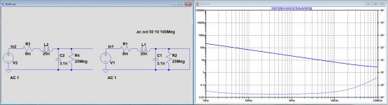
I was curious about the Townshend statement concerning their Isolda cable with a characteristic impedance of 8R.
L=20nH/m, C=3.1nF/m R=8m/m G=(1/25Meg)/m
A simple way to measure the characteristic impedance is Z0=Sqrt(Zopen*Zshorted).
Thats exactly what I did in LTspice.
See image below.
Only at 7Khz is the Char. Imp. equal to 8R.
When I haven't made a mistake, Townshend's claim is far from accurate.
Hans
L=20nH/m, C=3.1nF/m R=8m/m G=(1/25Meg)/m
A simple way to measure the characteristic impedance is Z0=Sqrt(Zopen*Zshorted).
Thats exactly what I did in LTspice.
See image below.
Only at 7Khz is the Char. Imp. equal to 8R.
When I haven't made a mistake, Townshend's claim is far from accurate.
Hans
Attachments
Last edited:
Audio Engineering Society Fellow, Jim Brown Wrote in a paper.
Transmission Lines at Audio Frequencies, and a Bit of History
If you study transmission lines in college or from the ARRL Handbook, you will learn the classic equation for characteristic impedance.
ZO= [ L/C) ]1/2
What most of us have long forgotten (and that few universities teach) is that this is the simplified form of the equation. In engineering classes, we make equations simpler by assuming certain conditions will be true for what we think will be the conditions when we use them. That’s fine as long as we don’t forget those assumption, but in this case, most of us have. The full equation for characteristic impedance is
ZO= [ (R+j2πfL) / (G+j2πfC) ]1/2
The formulas look much better in the paper:
http://www.audiosystemsgroup.com/TransLines-LowFreq.pdf
- Status
- Not open for further replies.
- Home
- General Interest
- Everything Else
- Analysis of speaker cables