I need a power stage plus driver to power a piezo-crystal based ultrasound transducer. The operating frequency is 1MHz and the waveform is a square wave of a duty cycle of 25% to 80%.
My initial idea is to use the NE555 IC to generate the square wave at 1MHz, a buffer stage consisting of an emitter follower, and a driver stage consisting of an emitter follower like those usually used for audio amplifiers. The output stage is thought to consist of an NPN and PNP complimentary transistors.
Since, I never built such a circuit I am asking the more experienced to avoid difficult to foresee electronic pitfalls.
The ultrasound power output needs to be known. A formula to calculate the ultrasound power for a driving square wave would be very much helpful and is appreciated.
What impedance is your piezo transducer at 1 MHz?
Do you straight drive it or there is a series coil tuning it?
In which case tank impedance is way lower and depends on Q
Your project is way more into the Industrial Electronics realm than into Audio, and not only because of the frequencies involved.
Do you straight drive it or there is a series coil tuning it?
In which case tank impedance is way lower and depends on Q
Your project is way more into the Industrial Electronics realm than into Audio, and not only because of the frequencies involved.
Last edited:
In the late eighties I was involved in the design and building of a sonic transducer array to measure the exact depths under a ship. The array made it possible to direct the sonic beam vertical by using computised delays in the individual transducers (near hundred) independent of the position of the ship due to wind, waves and swell. Things were controlled by a XT or AT computer, running at 8MHz and equipped with 512kB memory at least.
Anyhow, the array went stuck immidiate during the first shot. The near hundreds mosfet totempoles fired almost simultanious and produced such an amount of noise on any rail (power, control, ground, you name it) that the second burst (1/sec, continuous operation) never happened. Solution: short all the control rails with open collector digital bjt gates (nand's, nor's, whatever) during the shot and release them after. Military grade. I'm still in contact with the designer of this system (GB).
Anyhow, the array went stuck immidiate during the first shot. The near hundreds mosfet totempoles fired almost simultanious and produced such an amount of noise on any rail (power, control, ground, you name it) that the second burst (1/sec, continuous operation) never happened. Solution: short all the control rails with open collector digital bjt gates (nand's, nor's, whatever) during the shot and release them after. Military grade. I'm still in contact with the designer of this system (GB).
I created a 1MHz approx oscillator on LTSpice which seems to give a good quality sine wave output. I need to take an output from this oscillator without disturbing it. The oscillator is an old style LC and BJT based circuit.
Any ideas as to how I can produce a square wave from this oscillator are appreciated.
Thanks.
Any ideas as to how I can produce a square wave from this oscillator are appreciated.
Thanks.
Attachments
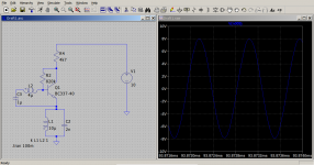
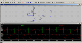
With two BJTs the circuit can produce a square wave of duty cycle of 50% approx. The circuit includes the oscillator operating at 1MHz and a sine to square wave converter. The next step is to design a power stage to power the piezo ultrasound transducer.
I am attaching an ltspice screenshot.
I am attaching an ltspice screenshot.
Attachments
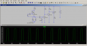
The attachment is the same circuit with four transistors one of which is a MOSFET. The output is a powerful 1A current pulse at around 1MHz. The duty cycle has been reduced below 50% to around 33%.
If anyone knows what I should add to the circuit to operate a piezo crystal to generate ultra sound waves at 1MHz, please post.
The purpose of this section is about electronics in general. There is no restriction to audio.
If anyone knows what I should add to the circuit to operate a piezo crystal to generate ultra sound waves at 1MHz, please post.
The purpose of this section is about electronics in general. There is no restriction to audio.
Attachments
A piezo crystal transducer has a parallel capacitance called the parallel parasitic capacitance. Its oscillatory action is represented electrically by a series RLC circuit in parallel with the parasitic capacitance. Since, a piezo crystal is a mechanical vibrator, it does work against anything surrounding it. The power transferred to its surroundings should affect the amplitude. For simplicity, I am assuming the resonant frequency remains unaltered as a result of power transfer. Electrically, this should mean the LC parts of the equivalent series circuit should remain unchanged under most conditions. The only parameter that seems to change when a crystal transfers energy to its surroundings is the series resistance. As a result of radiated energy, the crystal will oscillate with less amplitude presenting less resistance to the electrical source supplying it with electrical energy.
For any readers who may read this. The statement with the word 'assuming' is my assumption. I do not know whether it is valid or not for a crystal radiating power to its surroundings.
How I think the resonant frequency and the parasitic capacitance can be found:
a) The parasitic capacitance is in parallel with the crystal, so it should be readable with a meter.
b) The resonance is the mechanical natural frequency of the crystal. A tap on the crystal should stimulate it to generate an electrical signal with its natural frequency.
I do not know whether I will be successful. Without a proper LTSpice simulation I risk damaging the ultrasound transducer and I have to know its ultrasound power radiated.
The lack of previous knowledge of the piezo crystal transducer characteristics can be overridden by having a controlled output power of an adequate quality square wave at 1MHz. The crystal can be protected by gradually increasing a series resistance.
The attached screenshot is the resultant circuit with inexpensive components. Expensive components would make the entire project not viable and not worthy the expense. This equipment exists and can be purchased ready built.
The resultant output is a square wave of a rise time of 15ns and a fall time of 90ns. These times add to 105ns which is about 10% of the entire cycle.
Attachments
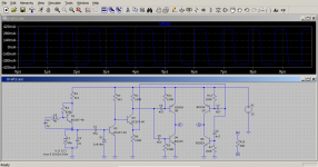
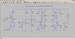
This is the final circuit which seems to be promising. The output square wave is neater compared to the previous resultant waveforms. The dissipation per transistor is within limits thanks to LTSpice's function which integrates the power dissipated in devices over a period giving the average power.
I am attaching the circuit which will be used to generate 1MHz ultrasound through the use of a piezo transducer.
I am attaching the circuit which will be used to generate 1MHz ultrasound through the use of a piezo transducer.
Attachments
- Status
- This old topic is closed. If you want to reopen this topic, contact a moderator using the "Report Post" button.
- Home
- General Interest
- Everything Else
- Power stage for piezo-crystal ultrasound transducer.