Hi, following the advice from a very kind Moderator of this forum i am quite decided about using dc-dc switching converters as psu.
The reason being that they switch very out of the audio band and potential residual ripple can be easily eliminated with "simple" passive filtering.
Therefore i am about to try a dc-dc switching regulator for a preamp i have at hand working with +/-24V voltage.
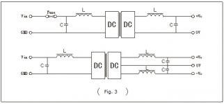
My question is ... will just one coil and a bypass cap to ground per rail, as in the pic attached, do the trick ?
Could someone kindly point me to a calculator for L and C values ?
Moreover ... better to place the filters close to the psu or the preamp circuit ?
Of course any advice would be very welcome
Kind regards, gino
The reason being that they switch very out of the audio band and potential residual ripple can be easily eliminated with "simple" passive filtering.
Therefore i am about to try a dc-dc switching regulator for a preamp i have at hand working with +/-24V voltage.
My question is ... will just one coil and a bypass cap to ground per rail, as in the pic attached, do the trick ?
Could someone kindly point me to a calculator for L and C values ?
Moreover ... better to place the filters close to the psu or the preamp circuit ?
Of course any advice would be very welcome
Kind regards, gino
Attachments
Last edited:
Whether a single LC stage is enough will depend on the output ripple of your DC-DC converter and the susceptibility to rail noise of your preamp circuitry.
LC filter calculators exist but they're generally for designing signal filters with specified load impedance. On a power supply filter the load impedance might not be known, or not well defined. You could have a try with : RF Tools | LC Filters Design Tool
LC filter calculators exist but they're generally for designing signal filters with specified load impedance. On a power supply filter the load impedance might not be known, or not well defined. You could have a try with : RF Tools | LC Filters Design Tool
Whether a single LC stage is enough will depend on the output ripple of your DC-DC converter ...
Thank you very much indeed for your kind and valuable advice. Just to be more precise this is the device i would like to try
5-30V to +-5V +-6V +-9V +-10V +-12V +-15V +-24V DC-DC Boost-Buck Converter New | eBay
i see from specs
For my task i need +/-24V to power a preamp of which i only know that has low distortion but i know nothing about its PSRR ... that could be not that greatworking frequency:180KHZ
The price of these devices is unbelievably low ... i wonder why no-one is interested by them. As i said at the beginning i was pointed to switching regulators and psu by a Moderator here in the forum
I have no access to a spectrum analyzer ... in the end it is my biggest regret
That instrument could tell something about their quality
Ok i admit to be lazy and mean ... but that price ...
and in order to get complete separation from the grid i could even use a 12V or lipo battery to power the converter i guess
I would love to hear from people who have actually tried them out
I understand that units like dacs and sound cards in particular actually use dc-dc converters to power the circuits and have very low noise.
Last edited:
I ran a quick simulation in LTSpice and came up with this filter.
L = 1mH Sumida CDRH127-LDNP102
C = 390uF/35V Rubycon ZLH
The inductor needs a series resistor to reduce the ringing, 0.68R reduced peaking to ~0.5dB. According to LTSpice at 180kHz you can expect about 90dB rejection, that's ignoring the parasitic capacitance of the inductor (coz I don't have that figure to hand).
Thank you very much indeed for your kind and very precious helpI ran a quick simulation in LTSpice and came up with this filter...
i really need to study this LTSpice ... power supplies are so intriguing to me
I have just played with it for sim two bjts circuits
but never dared to try power supplies my main interest sorry ... placed where ?The inductor needs a series resistor to reduce the ringing, 0.68R
great ! so very effective indeed... According to LTSpice at 180kHz you can expect about 90dB rejection, ...
Of course i do not have a complete noise spectrum of the regulator stage ... but i truly think i should give it a try I am pretty convinced that additional dc filtering is key to use these little devices in a line level applications
I really need to study LTSpice ... i do not know its limits ... but it looks like a very powerful design tool indeed. And as i said power supplies are my main interest
(Once i have nailed the psu then i could start thinking to some nice preamp circuits to try out with the psu ... )
Almost the only one
Thanks a lot again for your very kind and valuable advice
Kind regards, gino
Last edited:
sorry ... placed where ?
Its a series resistor which means its placed in series with the inductor. Meaning - R - L -. One side of the resistor connects to one side of the inductor. The new component then has two terminals - the unconnected side of the resistor, and the unconnected side of the inductor.
Thanks a lot again for your very kind and valuable advice
You're welcome.
Thanks ! and sorryIts a series resistor which means its placed in series with the inductor. Meaning - R - L - ....
but there were two options ... before or after the L Now it is completely clear ... an isolation resistor is placed before the stage that needs to be isolated
The circuits i have in mind are class A and they will draw very little current ... like 0.2A max no more
Just to chat a little i have a long term challenge with a friend ... i want to build a line stage that sounds better than his 2kUSD line stage
for not more than 1/10th of its price I have the strong feeling that i can do that because his tube line stage is strong on the midrange but quite weak on the bass. It is a cathode follower without voltage gain ... a tube buffer following an Alps Blue pot let's say
R before or after the L won't make a difference. I just chose an order randomly.
If you're DIYing a line stage then yes you should be able to do better for 10% of his cost, assuming he paid retail on boutique equipment. I'm ignorant about valves so have only the wildest guess why the bass on his line stage sucks - not low enough impedance power supply ?
If you're DIYing a line stage then yes you should be able to do better for 10% of his cost, assuming he paid retail on boutique equipment. I'm ignorant about valves so have only the wildest guess why the bass on his line stage sucks - not low enough impedance power supply ?
R before or after the L won't make a difference. I just chose an order randomly.

Yes ! he opted for the de-luxe champagne finish ... the wine finish was cheaperIf you're DIYing a line stage then yes you should be able to do better for 10% of his cost, assuming he paid retail on boutique equipment.
i can only say that we compared a solid state line stage with his tube line stage on a pipe organ track ... the solid state line stage shaked the walls the tube pre not at all .. the bass was like soft and not particularly extendedI'm ignorant about valves so have only the wildest guess why the bass on his line stage sucks - not low enough impedance power supply ?
Personally i find a simple sweep test at high enough volume a very telling tool to assess system response
For instance i have discovered that my desk speakers wake up at about 85 Hz and with no sound below that
I do not understand why testing with signals is not very popular among audiophile ... they prefer to use so called audiophile recordings
My friend loved his line stage ... after listening to the solid state preamp is a little puzzled
Midrange from tubes instead is quite nice ... very musical expecially with voices.
Thank you sincerely again. Next step to get a LTSpice for dummies book
Great software indeed.
- Status
- This old topic is closed. If you want to reopen this topic, contact a moderator using the "Report Post" button.
- Home
- General Interest
- Everything Else
- Kind advice needed on dc passive filtering