Radio frequency signals is an area where I am a tabula rasa as I have never built or tested anything with these frequencies.
This question is about a device which generates ultrasound waves using a piezo transducer. If I am not wrong, such devices use high DC voltages to generate enough acaustic energy. The device in question generates a maximum of 0.6W/cm^2. I would like to use a cable extension of about 1.5m to 2.0m between the square wave generator and the transducer. At present, these are connected with a short cable about 10cm to 12cm long.
I remember there is a rule of thumb in electronic engineering, which states an electronic current starts behaving like a wave, when its wavelength is about ten times as big as a transmission line or metal link. The effect becomes more and more pronounced as the wavelength shortens.
I am asking because an unmatched transmission line, when used with a frequency behaving like RF, can result in a wave whose amplitude increases until the RF generator is destroyed. I want to avoid this from happening.
At 1MHz assuming an electric field tranvels at the speed of light, the wavelength on the transmission line is 3e8/1e6 = 300m. A 2m long transmission line should only be 2/300=0.67%. According to this calculation, successive harmonics of the square wave above 1MHz should have enough accomodation up to 30MHz. For a square wave this should accomodate up to the 15th harmonic. In mathematics, using the first 15 terms in the Fourier Series should produce a good approximation to a square wave. However, this is all book theory: I am more interested in practice whether what I want is possible without destroying the source of square waves.
The cable I plan to use is a flexible microphone cable with a shield and a twin pair. I plan to use the shield as the ground and one wire of the pair as the signal. The other wire will be grounded at source but not at the piezo transducer.
Thanks for your patience.
Last edited:
The speed is inversely proportional to the square root of the product of the permittivity and permeability of the dielectric. What insulator is used in the cable?
When the cable is electrically short, you can treat it as a lumped series inductance or a lumped shunt capacitance, depending on whether the load impedance is small or large compared to the cable's characteristic impedance. I guess it is large, so then the cable adds some shunt capacitance. Can the generator handle that?
When the cable is electrically short, you can treat it as a lumped series inductance or a lumped shunt capacitance, depending on whether the load impedance is small or large compared to the cable's characteristic impedance. I guess it is large, so then the cable adds some shunt capacitance. Can the generator handle that?
What sort of generator is it? What amplitude of signal is at the generator output?
You may need a more suitable type of RF cable. The speed of propagation in the cable
will be somewhere around 0.6c - 0.8c. Bear in mind that the present short cable may be
tuned to the setup, and substituting another, longer one with different properties
could be problematic.
You may need a more suitable type of RF cable. The speed of propagation in the cable
will be somewhere around 0.6c - 0.8c. Bear in mind that the present short cable may be
tuned to the setup, and substituting another, longer one with different properties
could be problematic.
Last edited:
The circuit was working intermittently in the original package. I suspected the cause was a loose DC female connector at one end of the PCB. I remember a few years ago, I replaced this and the issue of intermittent function was resolved for quite some time. Now, the issue has resurfaced, and naturally, I suspected it was the same old ailment. However, opening and inspecting the PCB, I found the power transistor soldering to be the issue. There is a glaring dry joint on the emitter! The transistor is not a high voltage one, but with a Vce(max) = 30V and Vbc(max) = 40V, 60 <= beta <= 400, fT = 50MHz. The transistor part number is NEC D882 and is an NPN transistor.
I will solder the dry joint. If that cures all issues of intermittence, I will not need to do any modifications for this device.
I am attaching a photograph of the PCB showing the dry joint.
I will solder the dry joint. If that cures all issues of intermittence, I will not need to do any modifications for this device.
I am attaching a photograph of the PCB showing the dry joint.
Attachments

Last edited:
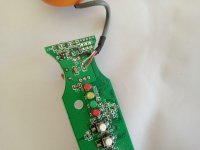
Sorry for the confusion, while inspecting the other side of the transistor pads, I found the solder is OK. This is a double sided PCB. This means, the trouble has not yet been resolved and I still need to use a cable for the piezo transducer.
As mentioned earlier, the power transistor is a NEC D882 NPN transistor. This is not a high voltage transistor but with a Vcb(max) = 40V. This transistor is rated at Ic(max) = 3A.
The piezo transducer has a diameter of 4cm which means an area of 12.6cm^2. At 0.6W/cm^2, the power emitted is 0.6*12.6 = 7.5W. The square wave maximum voltage cannot exceed 30V, so I am assuming a square wave voltage of 25V. This means, at 7.5W of power, a current of 7.5/25 = 0.3A. Although, these are very very rough estimates, this implies the working impedance is 25/0.3 = 83 Ohms or lower depending on whether the square wave goes negative and positive instead of 0V to positive 25V.
My very inexpert estimate is that the piezo transducer is matched to common cables of about 75 Ohms.
- Status
- This old topic is closed. If you want to reopen this topic, contact a moderator using the "Report Post" button.
- Home
- General Interest
- Everything Else
- 1MHz square wave transmission line question.