Hi to u all,
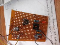
I built the circuit drawn below and it will not work.The circuit is so simple that to make sure all the components are sound(they were purchased new),i tested them in other circuits to ascertain their functionability.They performed well.The meter sensitivity is 150 microamperes and was removed from an old receiver that wasdiscarded as scrap.I measured some voltages on the circuit when it was powered by a 12 volt source dc.
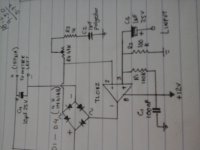
1)pin 1 of the TL082 was at 5.03volts
2)pin2 was at 1.42 volt
3)pin 3 was at 6.03 volts
Considering(1)&(3),the bridge is in unbalanced mode.Shouldn't that difference make the meters'needle deflect full scale and respond to the audio which was around 1.8 volt?Right now the cicuit behaves like a magnetic coil in that only when the circuit is first powered on did the needle make a short and brief movement before coming to rest in its initial position and would not respond to any other signal.I hope that with the info,u can help me in troubleshooting the circuit.thanks!
I built the circuit drawn below and it will not work.The circuit is so simple that to make sure all the components are sound(they were purchased new),i tested them in other circuits to ascertain their functionability.They performed well.The meter sensitivity is 150 microamperes and was removed from an old receiver that wasdiscarded as scrap.I measured some voltages on the circuit when it was powered by a 12 volt source dc.
1)pin 1 of the TL082 was at 5.03volts
2)pin2 was at 1.42 volt
3)pin 3 was at 6.03 volts
Considering(1)&(3),the bridge is in unbalanced mode.Shouldn't that difference make the meters'needle deflect full scale and respond to the audio which was around 1.8 volt?Right now the cicuit behaves like a magnetic coil in that only when the circuit is first powered on did the needle make a short and brief movement before coming to rest in its initial position and would not respond to any other signal.I hope that with the info,u can help me in troubleshooting the circuit.thanks!
Attachments
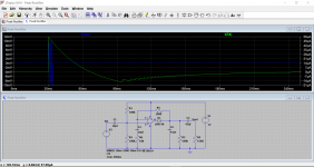
I did a half wave version for someone on the forum a long time ago...
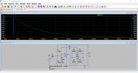
I've just altered it to full. The resistors R3 and R4 determine the current flow in the load and so need to be scaled to suit the meter. This shows the way it responds to a short duration tone burst.
I've just altered it to full. The resistors R3 and R4 determine the current flow in the load and so need to be scaled to suit the meter. This shows the way it responds to a short duration tone burst.
Attachments
So have a look at the circuit I posted above.
You need suitably low value resistors for R3 and R4 because this is the only path for the meter current to flow in. You may need to play around with the cap across the meter to get the kind of visual response you want.
It should work though.
You need suitably low value resistors for R3 and R4 because this is the only path for the meter current to flow in. You may need to play around with the cap across the meter to get the kind of visual response you want.
It should work though.
A reversed C3 (see post 4) might cause trouble. Check you have that right.
Where does pin 2 (inverting input) get its bias from when there is no signal to switch on the bridge? As it stands, it seems to me that the circuit will ignore smaller signals. Maybe you didn't try it with enough input?
Where does pin 2 (inverting input) get its bias from when there is no signal to switch on the bridge? As it stands, it seems to me that the circuit will ignore smaller signals. Maybe you didn't try it with enough input?
Low level operation is a possible issue on that circuit. Curiously the simulation shows all points to be at 6 volts which means the opamp input bias currents (its a 741 equivalent) aren't modelled.
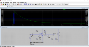
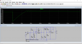
Perhaps the simpler version I originally did is better. This is with 1 volt and then 10 millivolts.
The load could also be returned to a fixed DC point as shown. Using a second opamp allows a low impedance reference point to be generated that also tracks the supply voltage. Its crude but effective.
Perhaps the simpler version I originally did is better. This is with 1 volt and then 10 millivolts.
The load could also be returned to a fixed DC point as shown. Using a second opamp allows a low impedance reference point to be generated that also tracks the supply voltage. Its crude but effective.
Attachments
TL082 is not a 741 equivalent. It has JFET inputs, so very small bias current.
Two things to try:
1. remove C4 - this stops stored charge confusing things
2. add a 1M resistor from output pin to inverting input pin, so it always has some bias
I suspect the circuit may be latching up because there is nothing to establish the right bias on the inverting input apart from diode leakage, and that has to charge up C2. Am I right in thinking that the usual version of this circuit uses the inverting opamp configuation? If so, why use the non-inverting version which adds complication?
Has the meter got inbuilt diodes like a VU meter.
What is the resistance of the meter.
Have you tried the pot on its minimum setting
1.8V peak or RMS ?
Do you have access to Schottky diodes (BAT 85 ) to replace the 1N4148 with , they have approx. 1/3 the forward voltage drop of the later .
What is the resistance of the meter.
Have you tried the pot on its minimum setting
1.8V peak or RMS ?
Do you have access to Schottky diodes (BAT 85 ) to replace the 1N4148 with , they have approx. 1/3 the forward voltage drop of the later .
No the meter has no inbuilt diodes.The only inscription i could read on its back is 150uA.I have tried every pot settings and even changed the pot configuration so that the cursor pin goes to the bridge ac input on pin 2 to no avail.The voltages measured are all dc with a digital meter.I got the schematic as i googled"needle meters for audio output"and in view all i picked the one which was simple to built which showed an interesting circuit.I used only one channel of the description as the meter was to be associated with a mono amplifier with 5 discrete transistors of surprisingly good sound(to my ears!).on the tl 082 pins 6 and 7 were left unconnected.
The circuit should have worked upon power on but did not.I have had some headaches to locate the fault but could not find it.mind you i have been testing a bunch of double Aops like NE5532,LM833,LM 1458 in place of the TL082,Aops which work fine in my heaphone amp and none of them could trigger the start.I will not be bothering myself anymore with it.I will do something else even though i am frustrated by that failure.I will go back to my text books to revise about integrators and see what went amiss but in the meantime i stay away from diy for a few days,thank u to u all who replied.
So the OP has lost interest in the circuit. I have not.
It has been said that R3 and R4 are the only way for the meter's current to ground. I do not see a way for DC to ground.
The meter must be feed fed with DC, that is what the rectifier is there for. I do not see any path for DC to flow through the meter.
It has been said that R3 and R4 are the only way for the meter's current to ground. I do not see a way for DC to ground.
The meter must be feed fed with DC, that is what the rectifier is there for. I do not see any path for DC to flow through the meter.
TL082 is not a 741 equivalent. It has JFET inputs, so very small bias current.
I was referring to the opamp I used in the simulation, the LT1001 which actually does have pretty low bias currents (single nano amp digit range) but it does have an appalling slew rate.
- Status
- This old topic is closed. If you want to reopen this topic, contact a moderator using the "Report Post" button.
- Home
- General Interest
- Everything Else
- Simple vu meter