OK.
The meter gets its DC from the AC via the bridge rectifier. No need for any 'DC path'.grommeteer said:I do not see any path for DC to flow through the meter.
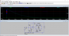
It might help you understand it if you look at the actual voltages when its in operation.
This shows 100mv peak AC input signal. Notice how the 'feedback voltage' is exactly the same as you would get if the bridge was removed and linked out.
The opamp driving voltage overcomes all the non linearities of the bridge because the bridge is enclosed within the feedback loop.
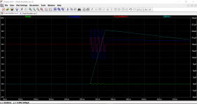
The meter and the cap across it can only charge at the rate determined by the feedback component values. It takes energy to charge the meter cap and that energy or current flow has to come from the current available via R3 and R4.
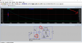
The last image shows increasing the feedback resistors by 100 times. Voltage wise nothing changes. The gain is still the same but now there is no current available for our meter and cap. Look at the scale at the right hand side for current.
This shows 100mv peak AC input signal. Notice how the 'feedback voltage' is exactly the same as you would get if the bridge was removed and linked out.
The opamp driving voltage overcomes all the non linearities of the bridge because the bridge is enclosed within the feedback loop.
The meter and the cap across it can only charge at the rate determined by the feedback component values. It takes energy to charge the meter cap and that energy or current flow has to come from the current available via R3 and R4.
The last image shows increasing the feedback resistors by 100 times. Voltage wise nothing changes. The gain is still the same but now there is no current available for our meter and cap. Look at the scale at the right hand side for current.
Attachments
Thank you Mooly for your explanations.
I was stuck in thinikng the actual current of the meter hat to flow through R3 and C2. It is of course only the current that charges C4 that goes through these components and it is of course an AC current. At 1kHz it doesn´t matter if C2 is 1uF or 100uF.
I have made my own LTSpice simulation and it gives me exactly the same result as in the pictures you attached. 20 µApeak for the meter with R3=1k.
You have done agreat job in getting my stubborn imagination on the right track.
Pity we did not find out why the OP´s feedback voltage ist way too low.......
- Status
- This old topic is closed. If you want to reopen this topic, contact a moderator using the "Report Post" button.