Here are two circuit examples that some other people might find useful.
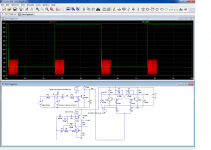
Both are toggle flip flops: the outputs change state for each active edge seen by the input (negative edges for these examples).
This type of circuit can be used for different purposes, like frequency division, but here the main goal is to emulate a ON/OFF switch.
Of course, they only provide a logic level that needs to be further processed/amplified to generate the desired action.
Why did I feel the need to reinvent a ~100 years old wheel? There are already hundreds, if not thousands of ICs doing just that.
A problem with existing IC's is that they fall broadly into two categories: dedicated power-control LSI's, proprietary, single source and including various bells and whistles, or logic IC's lacking an input conditioning.
The input-conditioning part is essential with logic ICs, because feeding them with unclean/uncontrolled transitions will lead to erratic behavior.
In principle, with CMOS the task should be relatively easy: use a schmitt trigger like the CD40106 in front of a flip flop like the CD4013.
This means two chips to do the job, but there is another problem: although the static power drawn by CMOS ICs is ~=0, the situation changes greatly when an input wanders between the supply rails.
In principle, gates with hysteresis are designed to operate in those conditions, but even them draw between 0.5 and 1mA when biased mid-supply.
As my application was a touch-control, this situation was inevitable, meaning CMOS were not actually micropower.
The circuits I designed consume ~100µA permanently, but they do not require additional power for the input conditioning: they can accept slow-changing, dirty input signals.
One variant, based on Q1 and Q2 is just the good old Eccles-Jordan with component values suited to the task.
The resistors values are very large, to reduce the current consumption (they could even be made significantly larger), and the capacitors are relatively large too, to tolerate slow varying input signals.
One advantage of this circuit is that the current consumption does not depend on the state.
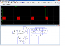
The other variant (Q4 Q5) is more original: it is a complementary FF reworked for toggle operation.
Since the two transistor are ON and OFF simultaneously, there is one state in which the current consumption is zero.
Both variants can be useful for specific applications.
Both accept the signal from a simplistic touch amplifier, Q3.
When an AC current is presented to its input, Q3 shorts C6, generating a negative transition.
This edge would be too slow and too unclean to be accepted by a regular logic IC, but both the versions presented are happy with it.
C5, the switch and the 90 meg resistor symbolize the human body.
The circuit is made sensitive enough to work with various types of devices under various conditions: in a class II equipment, there is always a small current/voltage present on the ground, and the human body being somewhat coupled to the earth, this causes a small current when the circuit is completed.
It would seem that this cannot work in conjunction with a class I (earthed) device: now, things work in reverse: the human body is coupled to 50/60Hz electrostatic fields, always present in a domestic environment, and this is normally sufficient to cause the 2.5µA necessary to trigger the circuit.
The circuit can also be used with directly mains-connected devices (with due precautions, of course).
In this case, it is necessary to replace R9 by a 220pF Y capacitor in series with a resistor of at least 4.7 meg rated at 300VAC at least.
Note that in all cases, the input wiring to the touch terminal needs to be minimal, and/or shielded, because of the sensitivity.
It also possible to replace Q3 with a conventional, momentary action push-button.
Needless to say that this touch system cannot work reliably in a pure, battery-operated environment.
Both variants have been tested, and the first one is in actual use (the constant current drain was preferable in my case)
Both are toggle flip flops: the outputs change state for each active edge seen by the input (negative edges for these examples).
This type of circuit can be used for different purposes, like frequency division, but here the main goal is to emulate a ON/OFF switch.
Of course, they only provide a logic level that needs to be further processed/amplified to generate the desired action.
Why did I feel the need to reinvent a ~100 years old wheel? There are already hundreds, if not thousands of ICs doing just that.
A problem with existing IC's is that they fall broadly into two categories: dedicated power-control LSI's, proprietary, single source and including various bells and whistles, or logic IC's lacking an input conditioning.
The input-conditioning part is essential with logic ICs, because feeding them with unclean/uncontrolled transitions will lead to erratic behavior.
In principle, with CMOS the task should be relatively easy: use a schmitt trigger like the CD40106 in front of a flip flop like the CD4013.
This means two chips to do the job, but there is another problem: although the static power drawn by CMOS ICs is ~=0, the situation changes greatly when an input wanders between the supply rails.
In principle, gates with hysteresis are designed to operate in those conditions, but even them draw between 0.5 and 1mA when biased mid-supply.
As my application was a touch-control, this situation was inevitable, meaning CMOS were not actually micropower.
The circuits I designed consume ~100µA permanently, but they do not require additional power for the input conditioning: they can accept slow-changing, dirty input signals.
One variant, based on Q1 and Q2 is just the good old Eccles-Jordan with component values suited to the task.
The resistors values are very large, to reduce the current consumption (they could even be made significantly larger), and the capacitors are relatively large too, to tolerate slow varying input signals.
One advantage of this circuit is that the current consumption does not depend on the state.
The other variant (Q4 Q5) is more original: it is a complementary FF reworked for toggle operation.
Since the two transistor are ON and OFF simultaneously, there is one state in which the current consumption is zero.
Both variants can be useful for specific applications.
Both accept the signal from a simplistic touch amplifier, Q3.
When an AC current is presented to its input, Q3 shorts C6, generating a negative transition.
This edge would be too slow and too unclean to be accepted by a regular logic IC, but both the versions presented are happy with it.
C5, the switch and the 90 meg resistor symbolize the human body.
The circuit is made sensitive enough to work with various types of devices under various conditions: in a class II equipment, there is always a small current/voltage present on the ground, and the human body being somewhat coupled to the earth, this causes a small current when the circuit is completed.
It would seem that this cannot work in conjunction with a class I (earthed) device: now, things work in reverse: the human body is coupled to 50/60Hz electrostatic fields, always present in a domestic environment, and this is normally sufficient to cause the 2.5µA necessary to trigger the circuit.
The circuit can also be used with directly mains-connected devices (with due precautions, of course).
In this case, it is necessary to replace R9 by a 220pF Y capacitor in series with a resistor of at least 4.7 meg rated at 300VAC at least.
Note that in all cases, the input wiring to the touch terminal needs to be minimal, and/or shielded, because of the sensitivity.
It also possible to replace Q3 with a conventional, momentary action push-button.
Needless to say that this touch system cannot work reliably in a pure, battery-operated environment.
Both variants have been tested, and the first one is in actual use (the constant current drain was preferable in my case)
Attachments
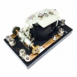
Simpler, though increasingly expensive:
Ratchet-relay. ZERO power consumption in either state. (Big WHUNK of power to switch, this is no touch-switch, but switching is typically rare.)
Not picky about debouncing.
I have one here, waiting to rig into my cellar lights.
Ratchet-relay. ZERO power consumption in either state. (Big WHUNK of power to switch, this is no touch-switch, but switching is typically rare.)
Not picky about debouncing.
I have one here, waiting to rig into my cellar lights.
Attachments
- Status
- This old topic is closed. If you want to reopen this topic, contact a moderator using the "Report Post" button.