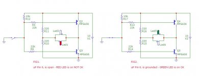
Both should be possible, or even none. Anyway, there is no need for an IC.Was using NPN and PNP for each LED feed.
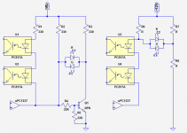
Here is an example with a NPN, current through the LEDs = 10mA (can be adapted by scaling the resistor's values).
On the right is an example using only resistors; to be able to use it, you'll need a comfortable enough supply voltage, 12V or more should be sufficient.
Attachments
If you look at the schematic i posted, the mosdriver isn't connected to the 74HC14, not needed.And with the HC version 10mA led current is easely reached with parallel outputs.
Mona
Yes, I noticed amendment, but please realise I'm using the 74AC14 device now and due to past issues with driving mosdriver plus other devices from same signal I presumed it would be better to have some form of buffer between what is 'essential' and 'indication' levels of function.
I was considering abandoning any 'fault indication' due to potential compromise last week. Now I have solution... cool... thanks to all.
Device cost is not an issue.... I'm not in production of 10,000 widgets.
High speed, High reliability of essential and indication function ...with
Low component count and board space the priorities.
So, it follows, given the de-rating of output device, [50% loading]
What merit is there, if any, in parallel connected invert gates driving the panel indicator LED other than using these redundant outputs in a hex package?
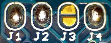
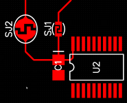
Arrange the PCB layout so that it's especially easy to try both variants of the circuit. Either by making a solder-bridgeable open circuit, or by laying out an intact trace that's especially easy to cut without injuring anything else nearby. Then try it both ways.
(Or perform the experiments in vitro using through hole components on a solderless breadboard, if you feel your perceptions and measurements in the lab are a good predictor of your perceptions and measurements in the audio salon on the finished gear.)
BTW another way to gainfully employ all N Schmitt Trigger inverters in a package, is to use two of them to make the H-bridge, one of them to provide teeter-totter antiphase operation, and the remaining (N-3) in cascade, to make awful damn certain the final outputs are slammed hard to a full logic level, despite unreliable and slow-moving input.
If you've never measured the DC gain of a CMOS logic gate (gain == slope of the Vout_vs_Vin curve == dVout/dVin), I recommend trying it. You'll be astonished.
Attachments
If you've never measured the DC gain of a CMOS logic gate (gain == slope of the Vout_vs_Vin curve == dVout/dVin), I recommend trying it.
Here are some measurements made on a CMOS logic gate with considerably less grunt than the 74AC14; this one is only good for about 3-4 mA rather than the muscular 24mA which the AC logic family guarantees: link .
Member
Joined 2009
Paid Member
Member
Joined 2009
Paid Member
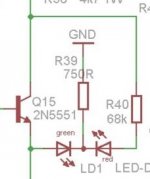
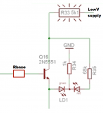
Took your advice Gareth, here is my take on the second para of post#1. You would have to calculate the resistor values depending on your supply voltage and the current you will allow through the LEDs. Hope it solves your problem "Shh its me"
Obviously when the power is off then no LED is on.")
Obviously when the power is off then no LED is on.
Attachments
Last edited:
Yikes you are right. I only read the first half of the first line! Please accept my apologies.Regrettably you didn't read properly the first line of the first post
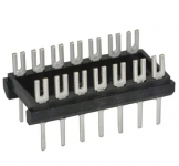
If you mounted the components on a DIP header like we used to do in the good old days of wire-wrap ('cause the only WW sockets were DIP sockets!), you could use the first 3 rows to mount the BJT, and the remaining 4 rows to mount the four resistors. Voila it all fits in the footprint of a 14 pin DIP. However the 68K resistance of R35 might make it a bit tricky to match the brightness of the left and right LEDs. The right LED gets, what, 180 microamperes?
_
Attachments
Member
Joined 2009
Paid Member
I'd be tempted to put it into Spice for the circuit conditions you have available and then tinker around to find what works - I'm lazy (I think you remember that !!). The circuit I posted was an excerpt from a dc-protection circuit and the resistor values were dictated by the surrounding circuitry - I think the collector was fed from the +ve rail of the amplifier so it was 40V or so. I like that DIP idea, keeps it simple.
Hmm, 40V/68K = 600uA of LED current which still seems mighty low, particularly for a "FAULT" annunciator.
The common-cathode bicolor LED with the lowest current rating on Digikey's site, was (this one) with Imax = 10mA.
The common-cathode bicolor LED with the lowest current rating on Digikey's site, was (this one) with Imax = 10mA.
Here's a circuit that I've used before, using a common cathode LED.
When the input is high, the left LED is on. When the input is low, the right LED is on.
https://www.digikey.com/schemeit/project/led-switching-VE3IA8O30260/
When the input is high, the left LED is on. When the input is low, the right LED is on.
https://www.digikey.com/schemeit/project/led-switching-VE3IA8O30260/
Last edited:
Yikes you are right. I only read the first half of the first line! Please accept my apologies
_
My apologies for poor phrasing.. like I say, 'driven to distraction' and posted at 2am in the morning.... with an even more distracting issue going on in the background [still not resolved and headed to an appeals Court.]
Took your advice Gareth, here is my take on the second para of post#1. You would have to calculate the resistor values depending on your supply voltage and the current you will allow through the LEDs. Hope it solves your problem "Shh its me"
This is similar to a circuit I considered and tried.
The 'problem' I have with this is the load of R10 and R11 [220 +220 ] across supply and more so the 'dead short' presenting if both transistors receive an oscillating base signal.
To prevent this 'dead short' I changed PNP to NPN and NPN to PNP, so if such signal occurred no conduction at all.
Still distracted and time poor , having that non-audio matter.
Schmitt triggers will attenuate weak oscillation and amplify strong oscillation.
Maybe you need to find an 8 pin microcontroller chip whose I/O pins have enough grunt to directly drive an LED. Now you can program the thing to detect and ignore an oscillating input. You can program the thing to remain in the same output state for at least X milliseconds (regardless of input), for whatever X you desire, thereby preventing rapidly oscillating outputs. You can program the thing to sample the input every N milliseconds, and only consider the input "valid" if it's been in the same state for Z consecutive samples. This effectively lowpass filters the input and disregards rapid oscillation / flutter. You can do whatever you want, and major changes to the "theory of operation" do not require re-layout of PCB or desoldering wick.
Consider the Microchip PIC12F1571 for $0.66 in qty=1. One 8 pin DIP, one current limiting resistor, and your bicolor LED. Done. With all of the anti-oscillation countermeasures your fevered brain can possibly invent.
Took your advice Gareth, here is my take on the second para of post#1. You would have to calculate the resistor values depending on your supply voltage and the current you will allow through the LEDs. Hope it solves your problem "Shh its me"
Obviously when the power is off then no LED is on.
Hello Nico,
are you aware if anyone has implemented your scheme?
I would like to incorporate this into my upc1237 circuit.
yours is better than e.g. http://hifimediy.com/download/Speaker_Protection_Circuit.pdf which only indicates either power on or fault condition.
regards
Prasi
Last edited:
Folks:
I'd appreciate some guidance on controlling bicolor LEDs. The designs discussed in this thread are interesting but I'm unclear about why they are superior to the design I've successfully used, pictured below. The design I've used only requires two resistors and half of a DPST switch. Is a more complicated approach more efficient or less susceptible to failure? I'm not trying to pick a fight -- I want to adopt the best available approach in future projects.
Regards,
Scott
Attachments
The design I've used only requires two resistors and half of a DPST switch.
That circuit looks real good to me, as long as the switch is already available..
- Status
- This old topic is closed. If you want to reopen this topic, contact a moderator using the "Report Post" button.
- Home
- General Interest
- Everything Else
- Bipolar LED driver circuit?