I designed this circuit as a sub part of a larger project, involving the measurement of the impedance of current sources.
I though it might be useful in and of itself, so I present it here - see attachment.
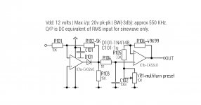
Description: This was based on an application note for the CA3140 MOSFET OP-Amp. It is unique in that it is a full wave rectifier that uses only one op-amp. On positive half cycles, the diode is reverse biased and the input passes through the 10k & 5K resistors and shunted by the 15K resistor. On negative half cycles the opamp output moves in the positive direction driving the inverting input toward ground by the action of negative feedback. By these means the positive cycles pass through and negative cycles are inverted with the net result of fullwave rectification. Note with these resistor values the output amplitude is half the input amplitude.
The second op-amp in the CA3240 is used as a buffer amplifier for the high impedance RC filter. The buffer amplifier in conjunction with a multiturn trimmer pot allows the output to be scaled correctly for a 1:1 relationship between AC RMS in and DC out. The voltage on C103 represents the average level of the rectified output from opamp 1. The time constant is quite long (100mSec) and can be made less, but with a corresponding increase in ripple on the DC output, also R104 should be kept around 1M as the output Z of the rectifier stage is uneven at 7K5 on positive half cycles and the output Z of the opamp during negative half cycles, so the load needs to be necessarily high so as not to upset the rectified output.
I though it might be useful in and of itself, so I present it here - see attachment.
Description: This was based on an application note for the CA3140 MOSFET OP-Amp. It is unique in that it is a full wave rectifier that uses only one op-amp. On positive half cycles, the diode is reverse biased and the input passes through the 10k & 5K resistors and shunted by the 15K resistor. On negative half cycles the opamp output moves in the positive direction driving the inverting input toward ground by the action of negative feedback. By these means the positive cycles pass through and negative cycles are inverted with the net result of fullwave rectification. Note with these resistor values the output amplitude is half the input amplitude.
The second op-amp in the CA3240 is used as a buffer amplifier for the high impedance RC filter. The buffer amplifier in conjunction with a multiturn trimmer pot allows the output to be scaled correctly for a 1:1 relationship between AC RMS in and DC out. The voltage on C103 represents the average level of the rectified output from opamp 1. The time constant is quite long (100mSec) and can be made less, but with a corresponding increase in ripple on the DC output, also R104 should be kept around 1M as the output Z of the rectifier stage is uneven at 7K5 on positive half cycles and the output Z of the opamp during negative half cycles, so the load needs to be necessarily high so as not to upset the rectified output.
Attachments
Last edited:
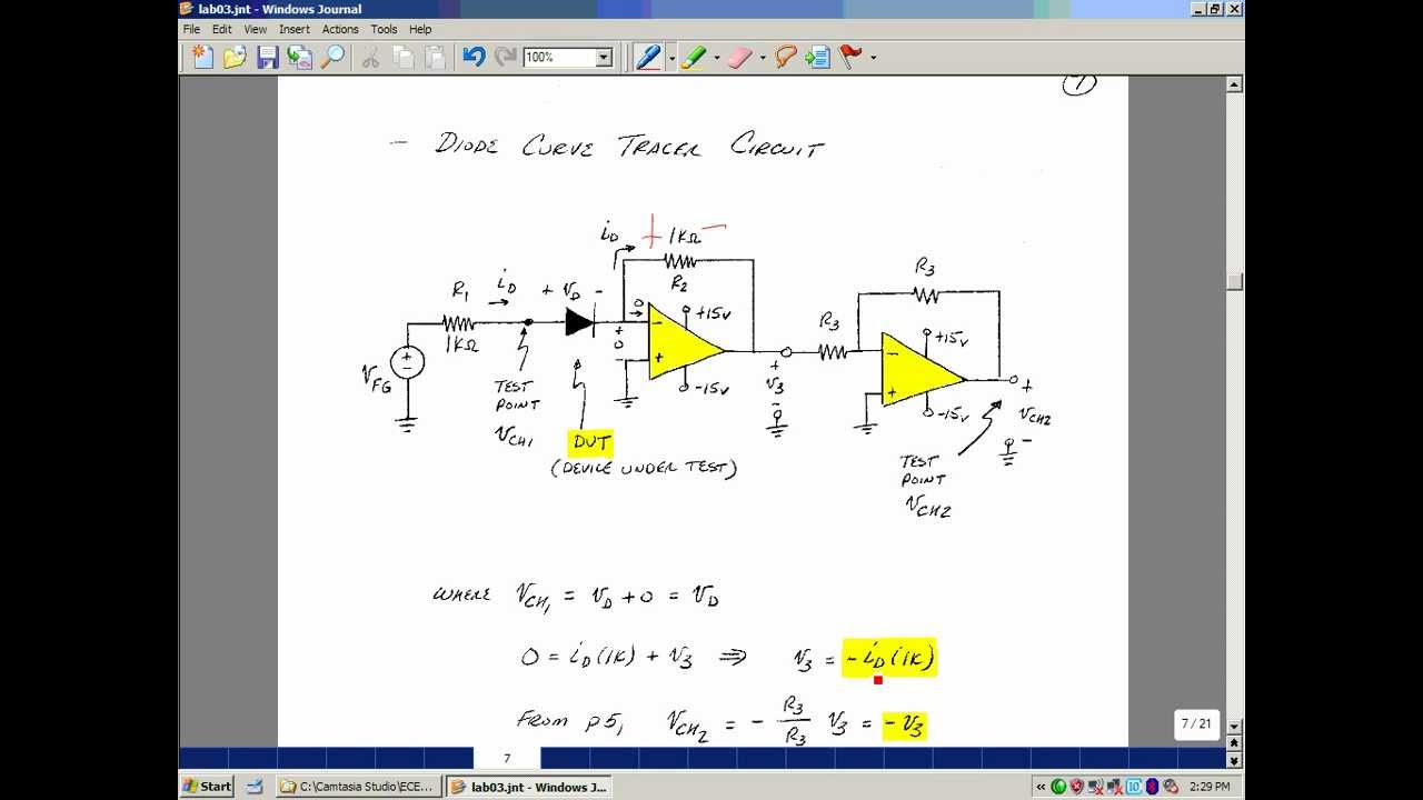
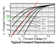
I recommend you round up a few candidates for D101 and put them on a curve tracer. You want one that remains solidly exponential beyond 5mA (with absolutely no reduction of exponential slope, caused by series resistance). In my testing the BYV10, PMEG3002, and ZLLS1000 all showed good stiff exponentials at currents far exceeding 5mA.
I also think it may be penny wise and pound foolish to use only two opamps. If you deployed the 2nd half of your fast BiCMOS opamp as a unity gain buffer (between IC1a output and R104) then you wouldn't have to worry about asymmetric drive strength for the two halves of the waveform, and you could select R104 without constraint. The third opamp can be a cheap-as-dirt LM358 since its input signal rolls off at 1.7 Hz; high bandwidth is not required.
I also think it may be penny wise and pound foolish to use only two opamps. If you deployed the 2nd half of your fast BiCMOS opamp as a unity gain buffer (between IC1a output and R104) then you wouldn't have to worry about asymmetric drive strength for the two halves of the waveform, and you could select R104 without constraint. The third opamp can be a cheap-as-dirt LM358 since its input signal rolls off at 1.7 Hz; high bandwidth is not required.
Mark, thanks for your suggestions, the second suggestion is no problem whatsoever and I'll probably will implement that. Don't have a curve tracer with which to test diodes. Would it be easy to build one that could display results on my oscilloscope, could be a useful thing to have.
Can you explain why the diode needs to have a near perfect exponential curve above 5 MA?
Gordon.
BTW the 3db point of the rectifier is around 550KHz, don't think I mentioned that in the first post.
Can you explain why the diode needs to have a near perfect exponential curve above 5 MA?
Gordon.
BTW the 3db point of the rectifier is around 550KHz, don't think I mentioned that in the first post.
Last edited:
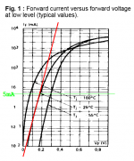
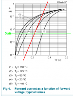
If the diodes match their datasheet curves (!) then putting them on a curve tracer is only a formality. The three aforementioned diodes's curves from their datasheets are shown below. BYV, PMEG, ZLLS in that order.
You want them to be exponential, i.e., you want them to be diodes, for fast settling. Hypothetically imagine a 1 megohm resistor in series with the diode; what effect does it have? Now slowly dial down the series resistance until it has no effect at all. That's the max resistance you can possibly tolerate; but you'd like even less.
Why 5mA? That appears to be an upper bound on the current your circuit will shove through the diode: 12V / (5K || 15K || 1Meg).
The curve tracer I use is a cantankerous old Tektronix 576, that I bought used for $400. When it works, it works very well.
Attachments
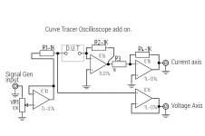
I'd suggest BD139+BD140 push pull emitter follower pairs on the output of IC1d and IC1a. The diode current flows through both of these amplifiers' output pins; if you want to measure currents higher than the opamp max (~20 mA) you will need external buffers. These remain inside the feedback loop so they have no effect upon accuracy at the low frequencies you'll use for curve tracing.
I also suggest you make R1 and R2 adjustable via rotary switches. Right now if you want to shove 20mA thru the diode, you'll need a 20 volt sawtooth. (20V / 1K) = 20mA.
I also suggest you make R1 and R2 adjustable via rotary switches. Right now if you want to shove 20mA thru the diode, you'll need a 20 volt sawtooth. (20V / 1K) = 20mA.
I'd suggest BD139+BD140 push pull emitter follower pairs on the output of IC1d and IC1a. The diode current flows through both of these amplifiers' output pins; if you want to measure currents higher than the opamp max (~20 mA) you will need external buffers. These remain inside the feedback loop so they have no effect upon accuracy at the low frequencies you'll use for curve tracing.
I also suggest you make R1 and R2 adjustable via rotary switches. Right now if you want to shove 20mA thru the diode, you'll need a 20 volt sawtooth. (20V / 1K) = 20mA.
The drive current won't be an issue as I'll be using the output of my signal generator rather than IC1d, I had thought about making R1 & R2 selectable to improve the versatility of the tracer. If I wanted to opt for higher test currents say ~ 1 A for power rectifiers IC1a & d might be better augmented using Darlington buffers.
Diode current flows through both R1 and R2. Ic1d sources the current and Ic1a sinks the current. If you replace Ic1a with a high current signal generator you still need to find a way to sink that current. Ic1a can only sink ~ 20mA
Yes of course because of KCL at the point of the inverting input, an equal but opposite polarity current must flow in or out of the o/p of IC1a through R2.
Gordon.
- Status
- This old topic is closed. If you want to reopen this topic, contact a moderator using the "Report Post" button.
- Home
- General Interest
- Everything Else
- CA3240 based precision rectifier