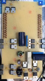
What are those squares on the buss? Less heat needed to change a connection? .......they definitely look like SMT ceramic capacitors - what size is that, is there a 2424?
They are 10 uF 50 V ceramic chip caps in 2220 size. These were given to me by one of the component reps, TDK or Murata, not sure which, when I was working on a high powered LTE transmitter for the 700 MHz band. They were bypass caps on the supply line to the RF output transistors. They were also used in the 12 to 28 volt boost converter.
Most ceramic capacitors exhibit a piezoelectric effect which works both ways. They can translate PC board vibrations into voltages, and they will turn current pulses into sound. We learned all about this during the development of the Nextel cell phones which exhibited a ticking sound as the transmitter was pulses on and off. These caps were designed to eliminate this.
I used them because they are excellent bypass caps for nearly all frequencies and I have a bunch. I put them on a board, or a breadboard with an ordinary soldering iron and 60/40 solder. Don't use that no-lead crap!
Ahhh, really?! I thought they might be copper squares. I once thought I was being pretty fancy by making a ground buss/plane from a piece of copper sheet cut into the shape of the space between all the components it served. I drilled holes all the way around the perimeter to take the wire leads. Turning out to be the shape of a paisley teardrop, all shined up it looked pretty spiffy. "Oooh , Art!" I thought, "right there in the chassis."
Then I learned how copper was a good conductor of more than just electrons. As I progressed inserting the wires around the edge it took longer and longer to heat the whole thing up , melting all the previous solder connections each time. By the end it was taking a couple of minutes for a connection.
Once I started making changes to the circuit I ended up making cuts at right angles to the edge between every connection to limit the heat transfer back into the plane - making it look like the top of a castle turret. It didn't work very well but was better than without. I wondered if maybe the squares above were a way of creating pads that could be de/re soldered without heating the whole bus so changes could be made with a small iron. Caps never entered my mind. Thanks.
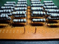
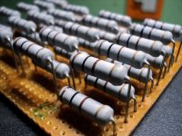
I made a similar load for testing the 28 volt boost converter mentioned above. It used 24 X of 15 ohm 10 watt resistors and miniature toggle switches to give 12 steps of 30 ohms each, roughly 1 amp per switch. The resistors were operated slightly over spec, so I mounted a 12 volt fan from a dead PC on the front of the board facing the resistors. It kept things cool with only 6 or 8 volts on the fan. I ran this thing a lot, often for hours at a time during the early development and prototype testing cycle. I called this device the "load bank."
Our group did advanced development of new technology. We designed the circuitry, and build a few "proof of concept" prototypes, tested and documented the prototypes, then turned the whole package including all but one of the prototypes to a product development group. We offered support to the product group as needed.
After a few weeks I hadn't heard from the product guys, so I walked over to their building for a look. They had redesigned the boost converter to make it "better" and nothing worked....including the load bank.
The white cement resistors that I used were all brown. So was the PC board. The resistance readings were off too, some banks were open. The resistors were not blown, the solder had cracked and become brittle from the heat conducted down the leads because they had not been using the fan.....it made too much noise. Fixing the load bank was easy, just resolder everything.
So, I offer this advice, if you are going to run yours anywhere near max power for more than a few minutes, keep some air moving across it. A 2 watt resistor can not dissipate 2 watts in the middle of the board surrounded by a field of similar heat emitters.
Fixing their boost converter was a different story. They had decided that there wasn't enough safety margin in the semiconductors that I had selected, so they swapped in the biggest mosfet and diodes in the On Semiconductor catalog. OK, you do not need, or want a 50 amp fet in a 10 amp power supply, because the driver can't switch a 5000pf gate at 1 MHz without making round square waves. Ditto the diodes. Rounded square waves melt parts!
I have made two new ones in the last month or so.
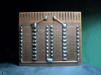
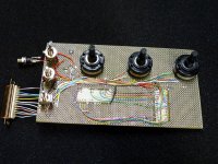
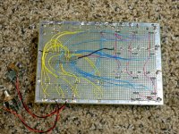
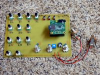
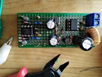
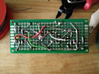
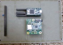
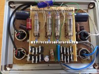
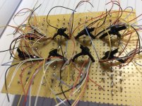
The first started out as the prototype for the sound box below. After it was used for that purpose, I ripped out the multi position switches and installed 3 rotary encoders, added 8 more pots, and rearranged them all, then it became a breadboard for a drum machine, which after a few more changes, became a music synthesizer. It is a 1V/oct synth with analog voltage control inputs, but the sound engine is digital, based inside an Arduino compatible 32 bit ARM Cortex M4 processor board and a 44/16 DAC board. The proto board is getting worn, but there are several more changes and experiments planned before I make a new one. The yellow wires are digital inputs from encoders or push buttons. The blue wires are analog inputs to the 16 bit ADC, from pots or CV and gate inputs. The purple wires are the 3.3 volt buss to all the pots.
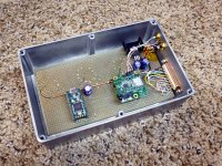
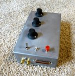
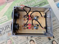
The second is a sound box for a military simulator. A friend is setting up some military surplus simulators for battlefield simulations. The surplus equipment is being reconstituted from several scrapped simulators, and I am helping fill in the missing electronics. This box is basically a WAV file player with several different triggers. I used the prototype to play drums, keyboards, and some other "instruments." This one makes machine gunfire, assorted explosions, and other battlefield sounds (whatever WAV's are on the SD card).
The first started out as the prototype for the sound box below. After it was used for that purpose, I ripped out the multi position switches and installed 3 rotary encoders, added 8 more pots, and rearranged them all, then it became a breadboard for a drum machine, which after a few more changes, became a music synthesizer. It is a 1V/oct synth with analog voltage control inputs, but the sound engine is digital, based inside an Arduino compatible 32 bit ARM Cortex M4 processor board and a 44/16 DAC board. The proto board is getting worn, but there are several more changes and experiments planned before I make a new one. The yellow wires are digital inputs from encoders or push buttons. The blue wires are analog inputs to the 16 bit ADC, from pots or CV and gate inputs. The purple wires are the 3.3 volt buss to all the pots.
The second is a sound box for a military simulator. A friend is setting up some military surplus simulators for battlefield simulations. The surplus equipment is being reconstituted from several scrapped simulators, and I am helping fill in the missing electronics. This box is basically a WAV file player with several different triggers. I used the prototype to play drums, keyboards, and some other "instruments." This one makes machine gunfire, assorted explosions, and other battlefield sounds (whatever WAV's are on the SD card).
Attachments
Last edited:
Wow no posts for nearly five years? has every one stopped using experimenter board? I thought I had posted my mic line driver circuit but apparently not.
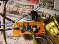
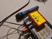
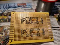
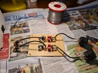
Anyway here is my latest. It's a quick and dirty preamp to boost the output from a wireless mic to decent levels when plugged into a normal amplifier. It's a bit rough around the edges but I was building it to a deadline so my normal faffing about for months or years didn't apply")
Tony.
Anyway here is my latest. It's a quick and dirty preamp to boost the output from a wireless mic to decent levels when plugged into a normal amplifier. It's a bit rough around the edges but I was building it to a deadline so my normal faffing about for months or years didn't apply
Tony.
Attachments
Last edited:
Wow no posts for nearly five years? has every one stopped using experimenter board?
Maybe my aging mind simply forgot about this thread.....now that you have reminded me, I do have about 5 years of perf board madness, some working, some already canabalized for parts. I have pictures of most.
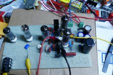
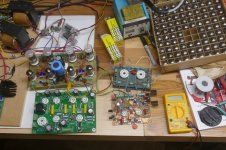
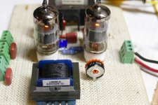
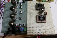
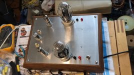
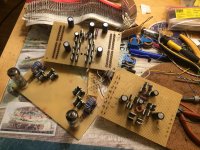
This picture shows the beginnings of a little guitar amp. It uses a push pull version of my UNSET topology. About a year ago when these pictures were taken the power amp section was built up and tested, mostly for more experience on the new technology. It squeezes 20 watts at 3% THD from a pair of tiny 50C5 radio tubes. I beat this thing up with an ADA MP1 guitar preamp, then let it run at 20 watts output overnight. It was making 20.03 watts the next morning.
The preamp circuitry will be copied from another of my DIY guitar amps when I find the time.
The design appeared in my UNSET thread here:
UNSET is coming?
The board is first mentioned in post#39, with the schematic and more info in post #57. Another member posted an LTspice file in post #62.
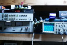
The perf board stuck between the scope and the power supply is my first pass experiment at the variable gain cell used in the Fairchild 670 compressor. It will become the Voltage Controlled Amplifier section in a vacuum tube music synthesizer, most of which will be prototyped on perf board. More on that in another post.
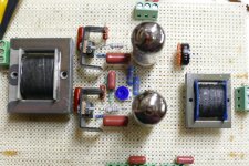
The whole UNSET concept started out as a push pull amp design three years ago. There is a 50 to 80 watt per channel amp board sitting behind one of my SPP boards (a 15 WPC EL84 amp). The perf board to the right was the very first implementation of the output stage. it is being driven by a hacked up driver board of my own design. They were used to refine the LT spice circuit into a working design that got implemented on the PC board with glowing tubes in it. It makes 50 WPC on an Antek toroid, and 80 WPC from a regulated power supply. This may become a Tubelab board at some time.
Attachments
Last edited:
When my 41 year engineering career at Motorola ended we packed up everything and moved 1200 miles on very short notice. A lot of "stuff" was sold, given away, or trashed. The rest was boxed up and moved, twice. Now 6 years later we are still finding unmarked "mystery boxes."
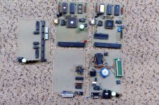
The digital synthesizer boards that I made in the 70's were seen earlier in this thread. These boards were from the late 80's and early 90's.
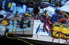
The pair in the upper right are EVB's of my own design to play with the then new MC68HC11 parts. Both are fully expanded systems with a "Buffalo" boot ROM, static RAM and an EEPROM for program storage. The big chip has internal EPROM and ram.
The board on the left is a digital timing generator, useful for making all the signals needed for NTSC video. A year or three later it all fit into a PIC16C54.
The board on the lower left is an FM demodulator and digital interface. I used it for some digital RF experiments......early wireless MIDI stuff that failed miserably.
The board on the lower right????? I know I made it, I can see that it contains a PIC16F877, a MAX232 serial port chip, a fat cap for memory backup, and an LCD display. What it did / does is lost somewhere in a deep dark corner of my brain.
The digital synthesizer boards that I made in the 70's were seen earlier in this thread. These boards were from the late 80's and early 90's.
The pair in the upper right are EVB's of my own design to play with the then new MC68HC11 parts. Both are fully expanded systems with a "Buffalo" boot ROM, static RAM and an EEPROM for program storage. The big chip has internal EPROM and ram.
The board on the left is a digital timing generator, useful for making all the signals needed for NTSC video. A year or three later it all fit into a PIC16C54.
The board on the lower left is an FM demodulator and digital interface. I used it for some digital RF experiments......early wireless MIDI stuff that failed miserably.
The board on the lower right????? I know I made it, I can see that it contains a PIC16F877, a MAX232 serial port chip, a fat cap for memory backup, and an LCD display. What it did / does is lost somewhere in a deep dark corner of my brain.
Attachments
Nice!
It had already lived it's useful life, so it simply got stuck in the first available cubbyhole.
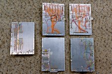
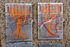
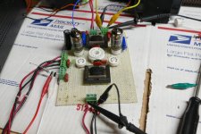
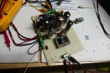
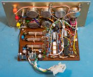
That board started out as a clone of the VGA cell in the Fairchild 670 complete with it's priceless 6386 tubes, but using low buck Edcor iron. I took benchmark data, then ripped it up and proceeded to try things. At one time it had 5 tube sockets on it and parts hanging on other part in mid air. The circuit is a balanced design, so that only two tubes, or one dual tube was used at a time. The circuit and tubes of choice changed often until I got what I wanted.
The first pic shows the 6386 version connected to my perf board rendition of a vacuum tube Moog style ladder filter. The second pic shows the board as it existed before I removed the tubes and shelved it. 5 tubes were stuffed into it for the pic, but it's could not be used that way. These are from mid 2019.
In January of this year I took it down from its precarious place where it slept, undamaged. (3rd pic) I popped in two tubes and verified that it still worked......carefully traced its circuit, then ripped it apart and rebuilt it.
The rebuilt version works far beyond what's needed in a music synthesizer, so I call it done. Now back to the vacuum tube VCF which has been sleeping in a box for even longer.
More info is in this thread:
Modular Synth build
It first appears in post #25, the finished version is in post #56
Attachments
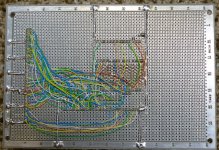
I'm always amazed by those early boards with computer chips and masses of wiring on the back! I guess the speeds were low enough not to be a problem back then.
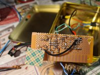
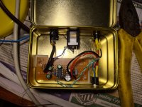
Here are some pics of the Mic Line driver I mentioned. Basically a circuit I designed to allow me to make up some electret mics and run them off the 48V phantom power on my focusrite 2i2.
It works very nicely. I posted a few recordings I did using it in this post Recording Software advice??
Tony.
Here are some pics of the Mic Line driver I mentioned. Basically a circuit I designed to allow me to make up some electret mics and run them off the 48V phantom power on my focusrite 2i2.
It works very nicely. I posted a few recordings I did using it in this post Recording Software advice??
Tony.
Attachments
I'm always amazed by those early boards with computer chips and masses of wiring on the back! I guess the speeds were low enough not to be a problem back then.... Tony.
My first computer was a SWTPC MC6800 system. It ran at a whopping 921KHz. The MC68HC11 chips used in my breadboard EVB's ran in the 2 to 4 MHz range. I built quite a few computer boards like this during that era. If you keep power and ground on rather wide or fat conductors with ample bypassing at every chip, the address and data busses seem to be OK as relatively equal length wire wrap wires. I don't think I ever tried to push these kinds of designs past 5 MHz.
In the late 70's I got mad at Motorola and left the company for a while to work for a computer company that build minicomputer systems for NASA. The state of the are then was 4 X 4 AMD 2901 bipolar ECL bit slice CPU's concatenated to create a 16 bit machine that ran at 16 MHz. Miles of wire wrap wire on large 16 by 16 inch boards connected up each chip. Even at 16 MHz there were "ghosts in the machine" especially in the Memory and I/O processor boards.
The pictures in post #56 of the modular synthesizer thread show three other perf board designs I made.
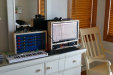
The power supply that I showed in post #138 of this thread is no longer big enough to run my modular synth, so it's now used for testing modules. The 7th picture in the synth thread shows it being used to test and calibrate a newly built sequencer module. The 9th picture shows it playing Blue.
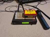
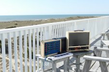
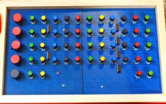
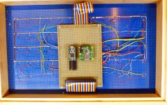
Blue is a completely digital synth that I made using a Teensy CPU board. It was originally designed for the Teensy 3.2, then upgraded to run a Teensy 3.6 for more power. The CPU and audio stuff is on a 4 X 6 inch perf board. The front panel is 10 x 16 inches of perf board with 4 rotary encoders, 49 pots and the associated multiplexing chips, and a few jacks and a push button. The encoders go to the digital inputs on the Teensy, while the pots are multiplexed to the analog inputs. The 1V/oct control voltage is applied to a dedicated analog input. The synth emulates an analog lead synth with 4 VCOs, two LFO's, two mixers, and two VCF / VCA / ADSR paths to a stereo output. Each path can draw from any or all of the 4 VCO's plus noise and external input. The hardware is pretty simple since all the work is done in software.
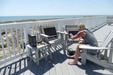
Blue would run for hours on one of those USB phone chargers or battery banks. That led to portable operation, an I even built a similar sized PC to match. The pair went on a few vacation trips, seen here overlooking the Atlantic Ocean in North Carolina.
I wanted something a bit smaller, but that's another story.
The power supply that I showed in post #138 of this thread is no longer big enough to run my modular synth, so it's now used for testing modules. The 7th picture in the synth thread shows it being used to test and calibrate a newly built sequencer module. The 9th picture shows it playing Blue.
Blue is a completely digital synth that I made using a Teensy CPU board. It was originally designed for the Teensy 3.2, then upgraded to run a Teensy 3.6 for more power. The CPU and audio stuff is on a 4 X 6 inch perf board. The front panel is 10 x 16 inches of perf board with 4 rotary encoders, 49 pots and the associated multiplexing chips, and a few jacks and a push button. The encoders go to the digital inputs on the Teensy, while the pots are multiplexed to the analog inputs. The 1V/oct control voltage is applied to a dedicated analog input. The synth emulates an analog lead synth with 4 VCOs, two LFO's, two mixers, and two VCF / VCA / ADSR paths to a stereo output. Each path can draw from any or all of the 4 VCO's plus noise and external input. The hardware is pretty simple since all the work is done in software.
Blue would run for hours on one of those USB phone chargers or battery banks. That led to portable operation, an I even built a similar sized PC to match. The pair went on a few vacation trips, seen here overlooking the Atlantic Ocean in North Carolina.
I wanted something a bit smaller, but that's another story.
Attachments
-
 P1210718_x.jpg709.8 KB · Views: 80
 -
 PC and Synth3_x.jpg440.7 KB · Views: 70
 -
 PC and Synth_1x.jpg454.5 KB · Views: 77
 -
 PC and Synth_2x.jpg468.5 KB · Views: 80
 -
 NuCPU_front_x.jpg690.5 KB · Views: 80
 -
 NuCPU_back_x.jpg878.4 KB · Views: 73
 -
 NewCPU_2_x.jpg805.9 KB · Views: 70
 -
 NewCPU_3_x.jpg607.8 KB · Views: 80
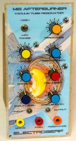
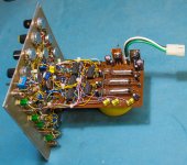
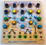
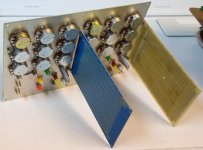
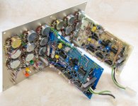
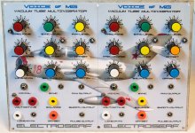
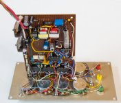
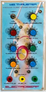
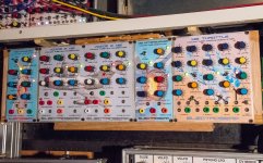
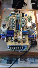
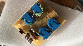
Over the winter I designed and built some analogue synthesizer modules using 1J24B Russian tubes on veroboard.
Take care,
Doug
Take care,
Doug
Attachments
-
 serfvcf2.jpg892.8 KB · Views: 64
 -
 serfvcf1.jpg390.2 KB · Views: 73
 -
 serfvca2.jpg604.7 KB · Views: 73
 -
 serfvca1.jpg650.2 KB · Views: 65
 -
 serfvco3.jpg625 KB · Views: 62
 -
 serfvco2.jpg705.6 KB · Views: 67
 -
 serfvco1.jpg651.5 KB · Views: 64
 -
 serfnoise2.jpg424.1 KB · Views: 61
 -
 serfnoise1.jpg380.5 KB · Views: 68
 -
 serfrack1.jpg967.6 KB · Views: 86
Zotl amps..
Attachments
Last edited:
Over the winter I designed and built some analogue synthesizer modules using 1J24B Russian tubes on veroboard.
Take care,
Doug
Coooool !!
Must be a pain.... fault finding if something breaks down... Let's hope not !
Zotl amps..
Your layouts look very nice and neat!
Coooool !!
Must be a pain.... fault finding if something breaks down... Let's hope not !
So far they've been 100% reliable. There is good access to both sides of the pcbs, so troubleshooting shouldn't be too difficult.
Take care,
Doug
- Home
- General Interest
- Everything Else
- Post Pictures of Your Vero Board Designs Here.