I just found this thread. Here is a blast from my past.....the distant past, like 40 years ago kind of past.
In the dawn of the IC logic era....CMOS wasn't even a dream......TTL was still research stuff.......DTL new stuff......there was RTL, the earliest form of integrated digital logic. The density was such that you got a flip flop or a single gate in a 8 pin TO-5 can. Starting with a weekly dumpster dive behind the Coulter Electronics (blood testing machines) factory I collected several hundred of these chips by blowtorching them from scrap boards. I made a fixture for testing them and then set out to build a little project.
I was awestruck by the antics of Keith Emerson after I saw ELP live and decided that I had to have a music synthesizer. Since they cost a ton of money and I had none, I decided to build it. I didn't want a simple voltage controlled analog synthesizer, I wanted a digital synthesizer, never mind that they hadn't been invented yet.
The machine took me 3 years to build. I started collecting chips in high school (1967 -1970) and the first sounds sprang forth in 1973. The tone generator boards use a total of about 350 RTL chips, all hand wired on perf board. That year I got a real job in the Motorola plant where I still work. There was a lot of overtime so there wasn't much time to work on the synthesizer, and I made good money, so I just bought an ARP Odyssey synthesizer and the mega chip monster sat neglected. It was eventually dismantled. The cabinet, huge linear power supply, audio mixing boards, and effects boards were tossed. The tone generator boards were a major piece of my life, so even after 40 years I still have them.
Attachments
Im A Perf-Board Pirate!
The Perf-Board is my canvas, the soldering iron is my brush, and the components are my paint. I'm an artist and a pirate! Here is evidence of some of my crimes over the last 35 years!
The Perf-Board is my canvas, the soldering iron is my brush, and the components are my paint. I'm an artist and a pirate! Here is evidence of some of my crimes over the last 35 years!
Attachments
Wow! That is... epic!
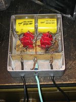
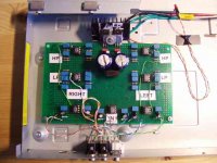
Here's my little recent project. I just wanted a circuit to replace a 6-position rotary switch with some momentary contact tactile switches, and some LED's to show which button was pushed. I wanted to put it all on one board but ran out of space so put it on 2; then I didn't have enough ribbon cable or Molex connectors so had to wire a bit of a rat's nest.
Here is my proof-of-concept prototype:

Here is the final circuit:

Here it is in the case:

Here's my little recent project. I just wanted a circuit to replace a 6-position rotary switch with some momentary contact tactile switches, and some LED's to show which button was pushed. I wanted to put it all on one board but ran out of space so put it on 2; then I didn't have enough ribbon cable or Molex connectors so had to wire a bit of a rat's nest.
Here is my proof-of-concept prototype:
Here is the final circuit:
Here it is in the case:
PiezoMatch
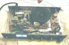
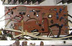
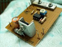
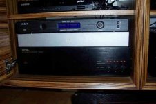
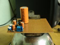
Here's a Piezo Cartridge-to-Line output impedance matcher that I completed a couple days ago. It's configured to load a crystal cartridge with 2.2 megs and drive line inputs down to about 3K or so.
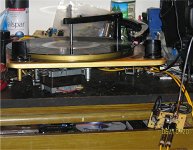
Mom had me empty the electronics out of an old 1958 Magnavox console. The Callero changer is massive in weight and construction. The cart and needle were in very good condition, so I cleaned and lubed her up. The PiezoMatch is extracting unbelievably good sound from that Callero. Must have been one of the few really great piezo cartridges ever made! That Callero should be performing on You Tube in the next few days.
The Perf-Board is my canvas, the soldering iron is my brush, and the components are my paint. I'm an artist and a pirate! Here is evidence of some of my crimes over the last 35 years!
Here's a Piezo Cartridge-to-Line output impedance matcher that I completed a couple days ago. It's configured to load a crystal cartridge with 2.2 megs and drive line inputs down to about 3K or so.
Mom had me empty the electronics out of an old 1958 Magnavox console. The Callero changer is massive in weight and construction. The cart and needle were in very good condition, so I cleaned and lubed her up. The PiezoMatch is extracting unbelievably good sound from that Callero. Must have been one of the few really great piezo cartridges ever made! That Callero should be performing on You Tube in the next few days.
Attachments
I just found this thread. Here is a blast from my past.....the distant past, like 40 years ago kind of past.
In the dawn of the IC logic era....CMOS wasn't even a dream......TTL was still research stuff.......DTL new stuff......there was RTL, the earliest form of integrated digital logic. The density was such that you got a flip flop or a single gate in a 8 pin TO-5 can. Starting with a weekly dumpster dive behind the Coulter Electronics (blood testing machines) factory I collected several hundred of these chips by blowtorching them from scrap boards. I made a fixture for testing them and then set out to build a little project.
I was awestruck by the antics of Keith Emerson after I saw ELP live and decided that I had to have a music synthesizer. Since they cost a ton of money and I had none, I decided to build it. I didn't want a simple voltage controlled analog synthesizer, I wanted a digital synthesizer, never mind that they hadn't been invented yet.
The machine took me 3 years to build. I started collecting chips in high school (1967 -1970) and the first sounds sprang forth in 1973. The tone generator boards use a total of about 350 RTL chips, all hand wired on perf board. That year I got a real job in the Motorola plant where I still work. There was a lot of overtime so there wasn't much time to work on the synthesizer, and I made good money, so I just bought an ARP Odyssey synthesizer and the mega chip monster sat neglected. It was eventually dismantled. The cabinet, huge linear power supply, audio mixing boards, and effects boards were tossed. The tone generator boards were a major piece of my life, so even after 40 years I still have them.
Nice to hear that.

...I didn't want a simple voltage controlled analog synthesizer, I wanted a digital synthesizer, never mind that they hadn't been invented yet.
The machine took me 3 years to build. I started collecting chips in high school (1967 -1970) and the first sounds sprang forth in 1973. The tone generator boards use a total of about 350 RTL chips, all hand wired on perf board.
Superb. More details please!
Superb. More details please!
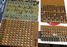
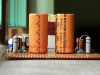
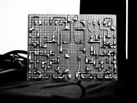
First off this all happened 40+ years ago and I was learning as I was building, so some of the mistakes that are obvious now, weren't so obvious to me then. Also as with most technology, these boards were reduced to simple circuits as the technology improved. Not all of the boards shown in the picture were used in the synthesizer at the same time. There are two tone generator sets. First a bit of background:
I started playing guitar at about 10 years old. Years of guitar lessons taught me a lot about music and the mathematical relationships between notes. My first DIY guitar amp happened when I stripped the wires in a guitar cord and twisted them to the wires in the tone arm of an old Magnavox HiFi set.
I got a dead Baldwin organ in high school. The tone generator in that organ was about 3 feet wide by a foot tall contained 36 6SN7 vacuum tubes and weighed about 40 pounds. Each 6SN7 tube contains two triode sections. 12 triodes were used as individually tuned oscillators to generate the 12 notes at the right hand end of the keyboard. These are the highest frequencies on the keyboard and are known as the "top octave". The remaining 60 triodes are used as frequency dividers to produce the 5 lower octaves on the keyboard by dividing the top octave by 2, 4, 8, 16 and 32.
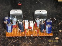
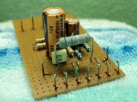
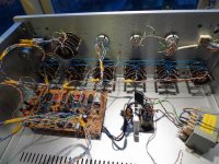
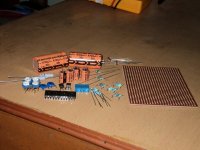
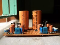
Note the similarity with the board in the lower left of the picture. The row of chips at the bottom of the board are 12 oscillators, each tuned by the trim pot to its corresponding note on the right side of the keyboard. Each of the other 36 chips on the board are flip flops configured as divide - by - two frequency dividers to generate a total of 4 octaves. I only had a 4 octave keyboard, so that's why I made a 4 octave tone generator board. This single board performed the same function as the 40 pound slab of steel and glass in the Baldwin organ.
I saw a magazine article in the mid 60's that proposed the idea that the top octave in a musical instrument could be generated by dividing a master clock frequency by 12 different numbers to generate each note. The notes in the musical scale are related by irrational numbers but thay can be approximated closely enough if you start with at least a 2 MHz clock. No problem today, but 2 MHz rated divider chips weren't common in 1965. Fortunately for me they were a dumpster dive away in 1969. Boards full of brand new chips that failed QC for some reason were tossed in the trash.
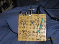
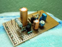
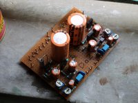
The green board in the upper right accomplishes that task. The discrete components and the black chip in the upper right are the master clock oscillator. It is voltage controlled allowing a master pitch bend wheel. I experimented with "theremin mode" so that you could play a chord on the keyboard with one hand, and bend it over a several octave range with the other hand. It sounded really cool, but was too unstable to be used in the real world.
The 48 chips on the lower half of the board make up the 12 dividers each configured by the yellow and black wires to divide by a fixed number. The components in the upper left were an experiment that led to the development of the other two boards. This board is known as a "top octave generator". In 1976 the Mostek corporation put an entire top octave generator on a single chip, the MK50240. That chip was an instant hit with experimentors but the chip and Mostek are just memories now. I still have some MK50240's around here somewhere. I was using them in guitars, but that is another story.
It is a simple matter to connect each note from the top octave to a string of dividers to make a complete tone generator, and I built one using a bunch of flip flop chips. But a tone generator alone doesn't make a synthesizer, it doesn't even make a good organ.
Most of us know that the difference in sound between say a guitar and a saxophone are the harmonic content, the attack and the decay of the notes. A music synthesizer allows adjustment of these parameters. The attack and decay are controlled by a vaiable gain amplifier controlled by a ramp generator that is triggered by touching the keyboard or an external trigger device. The common (back then) chip was the RCA CA3080. My VGA boards were long ago canabalized for their chips since CA3080's in the round metal can are quite rare today.
Most analog synthesizers start with a square or triangle waveform that is rich in harmonics and apply filtering to remove some or all of the harmonics to alter the timbre of the sound. This is known as subtractive synthesis. It is also possible to start with a pure sine wave tone at the fundamental frequency and sum in varying amounts of individual harmonics. This is known as additive synthesis and the best (albeit mechanical) methode for doing this in the old days were the drawbars on a Hammond organ.
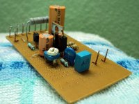
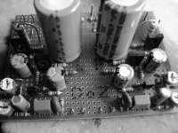
The other two PC boards start with a top octave in the ultrasonic region and divide it by 2, 3, 4, 5, 6 and 8 (board on lower left). The output of each divider can be summed into the final tone with slide pots (upper right). I learned two things. The old RTL chips are not fast enough to run the top octave generator in the 16 MHz range such that it will generate a top octave in the 50 KHz region. The top octave generator shown in the photo does actually run this fast so I could test the idea. I also learned that my math for the dividers was all wrong, but it sounded cool. There were some keboard matrix boards using about 1000 diodes that got tossed, some audio mixer and filter boards and a 10 pound power supply that all got dismantled for parts.
The machine was put together in several incarnations over a 2 year period or so. Some of them sounded cool, some never worked, and none were particularly reliable. From 1971 until 1973 I worked as the service tech at a stereo store next door to the University of Miami. They had a synthesizer lab with an ARP 2600. I could figure out how to program it (lots of patch cords) so, even though I wasn't a student I could go and talk to the music profs and get help on the theory. In 1973 I moved 40 miles north to get a "real job" and lost touch with the music lab.
Lots of overtime led to lost interest and the machine never got put back together after the move. The 4 boards are all that I have left. I have been photographing and tossing out many of my projects from the old days, but I kept those boards.
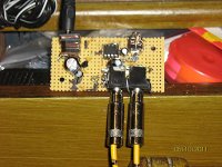
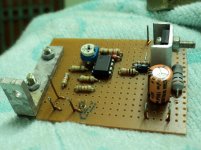
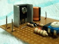
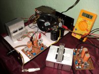
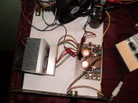
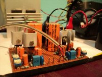
ESP's Thermo-Fan controller. This is a fun project! Especially when you see that you can start the fan by touching the sensing diode! Made for the Subwoofer amp. I didn't use it in my system though. Just used a LARGE heatsink and a fan at low but constant speed.
Link-> Thermo-Fan to keep your amplifier cool
.
Link-> Thermo-Fan to keep your amplifier cool
.
Attachments
First off this all happened 40+ years ago and I was learning as I was building, so some of the mistakes that are obvious now, weren't so obvious to me then. Also as with most technology, these boards were reduced to simple circuits as the technology improved. Not all of the boards shown in the picture were used in the synthesizer at the same time.
I love it.
I went through a not dissimilar process, but about 12 years later than you did. I, too, decided that VCOs were too flaky and built a master pitch-bendable VCO and divided it down digitally, but by that time you could buy programmable timer chips which made it a lot easier. I generated the audio waveforms from lookup tables in memory, and used analogue VCFs and VCAs. I made it as far as 6 voice polyphonic. Not as pioneering as you were, but I, too, ended up with a monstrous machine. I went through a lot of Veroboard, needless to say.
I still find it hard to believe that it was only another 10 years or so on from that that a standard PC could simulate the whole thing in software, and throw in a 32 track recording studio with all the effects for free.
Great thread - and respect  to all you peoples really nice works.
Maybe you know this situation:
I ofcourse would like to make real PCBs for my projects, but since the proto-types keeps on changing, I have somhow ended up in 10 years of veroboard making.
But hey: some of the first ones are still running great, so I guess it is safe enough.
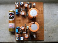
Here is my latest: Cello Audio Palette copy.
Vero-board densely populated for the equalizer-part.
to all you peoples really nice works.Maybe you know this situation:
I ofcourse would like to make real PCBs for my projects, but since the proto-types keeps on changing, I have somhow ended up in 10 years of veroboard making.
But hey: some of the first ones are still running great, so I guess it is safe enough.
Here is my latest: Cello Audio Palette copy.
Vero-board densely populated for the equalizer-part.
Attachments
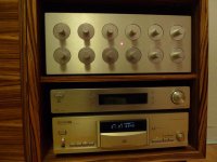
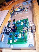
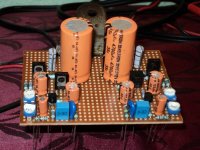
..and my 24dB Linkwitz Riley active crossover with OPA 2134 and 2% capacitors.
In the pictures it is a stereo two-way. It has later been expanded to a stereo three-way. Works and sounds excellent, and is by far the biggest upgrade one can do: Go active! Then you can also benefit from some of all your other DIY amps
(cabinet is an old DVD player)
In the pictures it is a stereo two-way. It has later been expanded to a stereo three-way. Works and sounds excellent, and is by far the biggest upgrade one can do: Go active! Then you can also benefit from some of all your other DIY amps
(cabinet is an old DVD player)
Attachments
I still find it hard to believe that it was only another 10 years or so on from that that a standard PC could simulate the whole thing in software, and throw in a 32 track recording studio with all the effects for free.
Today you could do all the hardware in a FPGA or write code for a DSP chip. I have tinkered with both (no vero board though) but don't have time for every project, so I sold most of the synthesizers except for a Roland JV1000 which my daughter left behind when she moved out. Now I use Cakewalk Sonar for most of my music tinkering. Most of my DIY building is confined to audio amps and RF stuff.
I have a friend who started out building a modular analog synth a few years ago. Now it takes up much of the living room. The chips used today are far more stable than the stuff of old. It is impressive and sounds awesome. Here is a link to info about his DIY ARP2600 with some MP3 files of it playing.
electro-music.com :: View topic - DIY ARP-2600 Modular Synthesizer
..and my 24dB Linkwitz Riley active crossover with OPA 2134 and 2% capacitors.
In the pictures it is a stereo two-way. It has later been expanded to a stereo three-way. Works and sounds excellent, and is by far the biggest upgrade one can do: Go active! Then you can also benefit from some of all your other DIY amps
(cabinet is an old DVD player)
That looks nice.
Great thread - and respect
Maybe you know this situation:
I ofcourse would like to make real PCBs for my projects, but since the proto-types keeps on changing, I have somhow ended up in 10 years of veroboard making.
But hey: some of the first ones are still running great, so I guess it is safe enough.
Here is my latest: Cello Audio Palette copy.
Vero-board densely populated for the equalizer-part.
Wow! 10 ICs on a vero? Bravo!
- Home
- General Interest
- Everything Else
- Post Pictures of Your Vero Board Designs Here.