Hi,
http://www.diyaudio.com/forums/everything-else/120687-oscilloscope-audio-tutorial.html
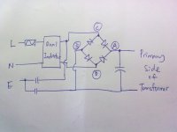
After reading the post above, i would like to ask how could i measure the 4 point of the diagram below by using an oscilloscope? My problem is i dont know which ground should i refer to for the primary part so that my black color wire from my probe which is probably the earth should connect to.
For example i should get a ripple waveform from the POINT B. so where should i clip my black wire of my probe to?
Can i clip it to the earth of the main?
I had got some advice which ask me to use an isolating-transformer. But it seems like not possible for me to buy it.so what else can i do to have a look on the waveform at the primary side?
thank you.
http://www.diyaudio.com/forums/everything-else/120687-oscilloscope-audio-tutorial.html
After reading the post above, i would like to ask how could i measure the 4 point of the diagram below by using an oscilloscope? My problem is i dont know which ground should i refer to for the primary part so that my black color wire from my probe which is probably the earth should connect to.
For example i should get a ripple waveform from the POINT B. so where should i clip my black wire of my probe to?
Can i clip it to the earth of the main?
I had got some advice which ask me to use an isolating-transformer. But it seems like not possible for me to buy it.so what else can i do to have a look on the waveform at the primary side?
thank you.
Attachments
Hi,
http://www.diyaudio.com/forums/everything-else/120687-oscilloscope-audio-tutorial.html
After reading the post above, i would like to ask how could i measure the 4 point of the diagram below by using an oscilloscope? My problem is i dont know which ground should i refer to for the primary part so that my black color wire from my probe which is probably the earth should connect to.
For example i should get a ripple waveform from the POINT B. so where should i clip my black wire of my probe to?
Can i clip it to the earth of the main?
I had got some advice which ask me to use an isolating-transformer. But it seems like not possible for me to buy it.so what else can i do to have a look on the waveform at the primary side?
thank you.
If you connect a transformer to the DC output of that bridge, be prepared for smoke and exploding diodes. You really should use an isolation transformer and then it's dangerous if you don't know what you're doing. The fact that you're asking these questions means you're not stupid but also not ready to be measuring the primary side. Stay on the secondary side at first. The voltages are lower (at least for solid state low power amps and preamps).
In theory you can clip your scope 'ground to the neutral IF YOU KNOW WHICH ONE THAT REALLY IS. Not all buildings are wired to code. You CAN let the ground _float_ if connected to a grounding outlet since the scope ground is already connected to the third wire ground. You can prode the othe 2 lines directly and only the 'hot' lead will be active but this assumes the building is wired to code. Do us all a favor and NOT try this. It's not the best place for newbies and uncertainty causes mistakes and can be lethal.
G²
At all times remember two very basic things...
1. The 'scope is "just" a voltmeter.
2. The negative of the 'scope lead will (should) be connected to the case of the instrument and to mains earth... which has major implications as to what you can and can't connect to. You MUST remember what that means. That the scope negative lead is the same as a piece of wire from earth in the mains plug to the probe negative.
If you have an amp for example that's earthed and the zero or circuit ground is connected to that earth (just a normal commercial product) and you connect the scope to chassis that's fine. Connect the scope negative to a PSU rail (or anything other than ground or "chassis" and you have just put a dead short across it.
You must understand and visualise that.
Then there are the subtleties... that the above mentioned negative lead means that you can't connect the 'scope ground to sensitive or high impedance points as you might a DVM... it would cause major interaction with the circuit you are measureing... assuming grounding mentioned above wasn't an issue.
So to your question... measuring the primary side... I would advise anyone without the knowledge or expertise NOT to attempt that.
The obvious measurement is ripple across the cap... so 'scope ground to neg end of cap, AC coupled and measure ripple.
Leaving the scope ground put you can measure to the other points too.
You can measure across the secondaries directly... as long as you understand you are connecting one side to ground by doing that via the scope lead... and in the circuit AS SHOWN that would be OK... but NOT if any other point is connected to mains earth.
Tip... if are scared something might go pop, measure on a DVM on both AC and DC that there is no real potential between where you want to connect the scope negative to. And then as a safegaurd first use a 100 ohm 1/2 watt or so resistor in series with neg lead.
Last edited:
The obvious measurement is ripple across the cap... so 'scope ground to neg end of cap, AC coupled and measure ripple.
i would like to upload a full schematic for the primary side.below is the attach.

Do u mean by measure the ripple in such way?
thank you.
what's this? A suicide thread?
You need TWO isolation transformers (both without fedthrough PE!).
One for the scope and one for the DUT or at least an isolated differential probe.
regards
You need TWO isolation transformers (both without fedthrough PE!).
One for the scope and one for the DUT or at least an isolated differential probe.
without isolation transformers that way results in halfway rectification in most countries making the ripple measurement useless.Do u mean by measure the ripple in such way?
regards
NO!!!Do u mean by measure the ripple in such way?
thank you.
Points A, B, C and D are all at high voltage.
You should not connect the black (earth) wire to any of those.
You can clip it to earth of the mains as you said first.
Come on people dont give advice unless you are certain
No!! use only ONE iso transformer on the DUT only. If u float the oscope from PE earth then oscopes bench chassis becomes very dangerous poking around the primary! Think if someone walks up and touches the scope while its gnd clip is connected to the line side. If you use no isolation device the worst thing is u burn a ground clip and blow a fuse, this is safety in action , protecting a novice.
Using O-scopes 2 channels for differential measurements is good advice. Using a battery powered DVM is the best advise for novices.
what's this? A suicide thread?
You need TWO isolation transformers (both without fedthrough PE!).
One for the scope and one for the DUT or at least an isolated differential probe.
without isolation transformers that way results in halfway rectification in most countries making the ripple measurement useless.
regards
No!! use only ONE iso transformer on the DUT only. If u float the oscope from PE earth then oscopes bench chassis becomes very dangerous poking around the primary! Think if someone walks up and touches the scope while its gnd clip is connected to the line side. If you use no isolation device the worst thing is u burn a ground clip and blow a fuse, this is safety in action , protecting a novice.
Using O-scopes 2 channels for differential measurements is good advice. Using a battery powered DVM is the best advise for novices.
so where should i clip my black wire of my probe to?
I had got some advice which ask me to use an isolating-transformer. But it seems like not possible for me to buy it.so what else can i do to have a look on the waveform at the primary side?
thank you.
If you cant get an isolation transformer (note for floating the DUT only) connect oscope gnd ONLY to earth. Otherwise STOP untill you get one or find out Y u need one. This thread is becoming a public hazard.
with only one isolation transformer, the scopes ground set other parts of the DUT to live where you don't expect it, which is not good too.
regards
Yes u are possibly changing the measurement but at least its not a safety hazard.
You are making a PE connection to the DUT circuit when ever u connect the probes common so what.
using two transformers is no safety hazard as the floating voltage is earthfree.
regards
so what? You may set the case of the DUT to live. Touch it and prepare to be bitten.You are making a PE connection to the DUT circuit when ever u connect the probes common so what.
regards
i would like to upload a full schematic for the primary side.below is the attach.
View attachment 154904
Do u mean by measure the ripple in such way?
thank you.
No dont do this unless u have an isolation transformer (note u are only a diode away from the AC primary)
This thread is already become much too dangerous for this level of dialog!
This is Basic lab safety 101 ( I can't believe this JK I'm having this level of talking here)using two transformers is no safety hazard as the floating voltage is earthfree.
so what? You may set the case of the DUT to live. Touch it and prepare to be bitten.
regards
Yes u are right but you should advise any persons entering the LAB that touching DUT items under measurement is potentially hazardous.
But most people expect the test equipment to be safe to point at and move dials and such.
Yes but even some multimeters are connected to the line with no isolation.
Use battery DVMs to be specific
Use battery DVMs to be specific
Using O-scopes 2 channels for differential measurements is good advice. Using a battery powered DVM is the best advise for novices.
- Status
- This old topic is closed. If you want to reopen this topic, contact a moderator using the "Report Post" button.
- Home
- General Interest
- Everything Else
- How to measure waveform at the primary side?