thank you anatech - more things to keep in mind. I'll pass along whatever comes about just in case anyone else finds this of interest.
It's not really audio related; but then again, when I consider it within the realm of current sensing apparatuses, a paper cone connected to a wound bobbin within a magnetic field isn't really too far removed! No wonder I drew so much constructive comment.
It's not really audio related; but then again, when I consider it within the realm of current sensing apparatuses, a paper cone connected to a wound bobbin within a magnetic field isn't really too far removed! No wonder I drew so much constructive comment.
You know bluebeard,
Unless you're going build a zillion of these... for your own reasons... I would really look into a FLUKE current clamp... everything you need... already DONE. It shouldn't be that hard then to figure out the signal etc... plenty of geeks around here to design an interface amp (gain and offset)...
If you must go through the agony of building your own, there are toroids that will slip right over a MIG/TIG torch without an "opening mechanism... just a thought...
")
Unless you're going build a zillion of these... for your own reasons... I would really look into a FLUKE current clamp... everything you need... already DONE. It shouldn't be that hard then to figure out the signal etc... plenty of geeks around here to design an interface amp (gain and offset)...
If you must go through the agony of building your own, there are toroids that will slip right over a MIG/TIG torch without an "opening mechanism... just a thought...
Not a zillion, but I hope to make a couple of dozen. You're right about the Fluke route (one of the more ironic company names eh?). They were even among the places I emailed for information along the way. The clamp is a couple of hundred dollars. There are in fact a few other ac/dc Hall Effect sensors/switches out there that are somewhat less than that. Unless I can make this for less than 15usd in parts, it just wouldn't be a practical avenue for me to take in this project. I'd have to find some other way of sensing current in the wire, or arc at the torch.
Maybe this is of help: http://www.lem.com/docs/products/FHS 40-P SP600.pdf
No need for a ferrite core then. Simply make a PCB that you can attach to the high current busbar. Mechanical stability is mandatory.
No need for a ferrite core then. Simply make a PCB that you can attach to the high current busbar. Mechanical stability is mandatory.

for a clamp on concentrator no cutting is needed if you use U-I core, can adjust the gap to standardize sensitivity when setting it up
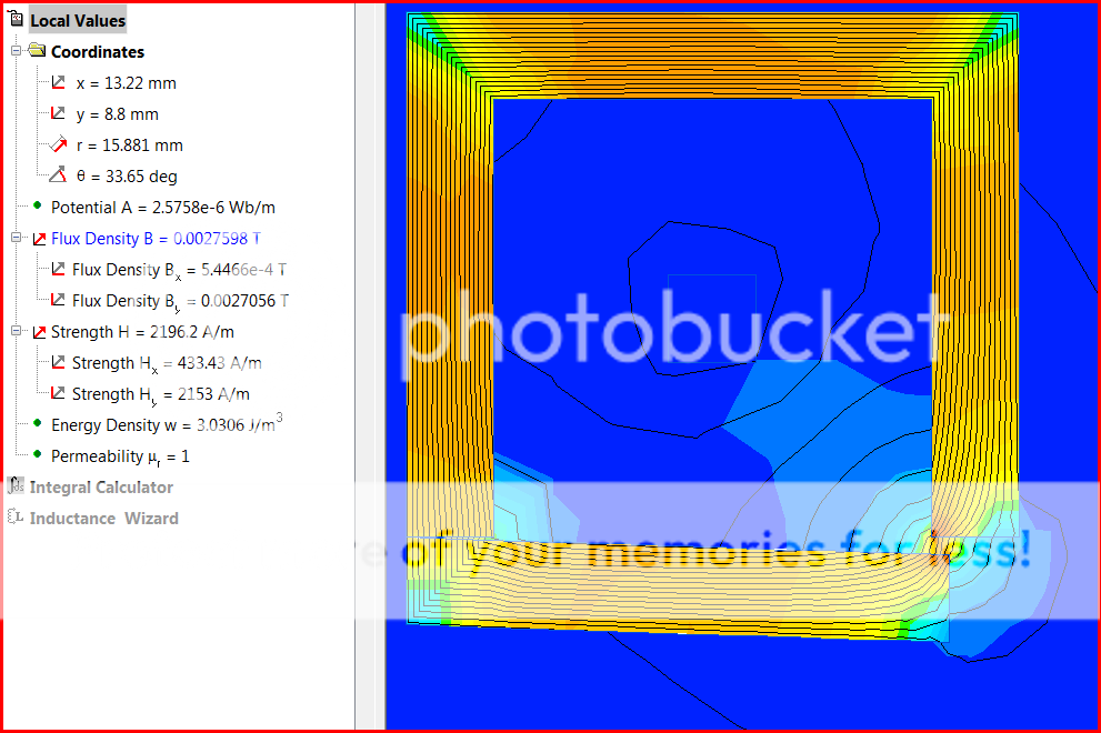
10x10mm core opening 2-D field sim:
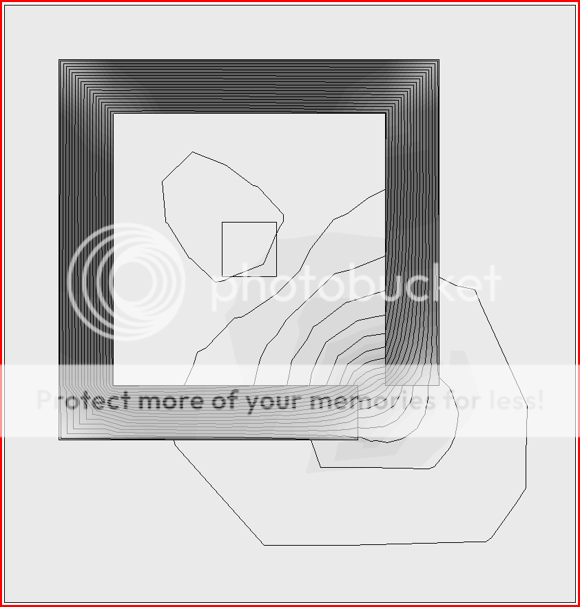
I get ~ 1 mT in the air gap with the 1mm offset I bar, 2 A current, u_r 100, but I'm no expert with this software
2-D ignores fringing field from Z axis truncation so field values might be lower, although grinding a taper could more than make up the leakage if your concentrator is much wider in the Z direction than the sensor element
remember you need low hysterisis magnetic material, and sensor
sensor sensitivity, hysterisis and Vos tempco can limit your low current resolution
ground/polished faces aren't really important when you have 1mm+ intentional air gap dimensions to fit sensor body
Student QuickField (free, <256 mesh nodes)
http://quickfield.com/
10x10mm core opening 2-D field sim:
I get ~ 1 mT in the air gap with the 1mm offset I bar, 2 A current, u_r 100, but I'm no expert with this software
2-D ignores fringing field from Z axis truncation so field values might be lower, although grinding a taper could more than make up the leakage if your concentrator is much wider in the Z direction than the sensor element
remember you need low hysterisis magnetic material, and sensor
sensor sensitivity, hysterisis and Vos tempco can limit your low current resolution
ground/polished faces aren't really important when you have 1mm+ intentional air gap dimensions to fit sensor body
Student QuickField (free, <256 mesh nodes)
http://quickfield.com/
Attachments
Here's a decent representative page of what I've found out there commercially.
http://www.bbautomacao.com/home_Open_Loop_Sensors_with_Round_Windows.html
Interesting particularly since the split core devices only begin at the 100amp sensitivity range. Below that, and into the milliamps, are the solid core. The prices on these are pretty reasonable as well. I see pages like this and it lures me into deeper and deeper google rabbit holes in the hope that I'll find my holy grail.
But I worry that perhaps the absence of lower current split core versions may indicate that the core consists of some form of non separable windings around the core. Maybe this can't be done?
While a lot of people have told me this might be difficult to do, nobody so far has strictly disabused me of the idea.
jcx, isn't the U I core merely another iteration of a split toroid (functionally). I'd prefer the split core ferrite since I can get them with nylon housings hinged and snapped (I suppose the U I cores can be similarly purchased, but is there any advantage to them over the 'C' cores?
I'd rather not have to fixture and grind brittle 1/2 round shapes when I can buy the U-I pieces
the sensing gap can be easily adjusted by sliding the I bar
the offset square corners give a natural wedge for higher flux concentration
one possibility:
glue a hall sensor on the end of the I bar, with the hall element aligned/centered on the corner/edge where my field plot shows the greatest flux concentration
then put the I bar + sensor (wired to the sensor cable) in a "boat", coat the U legs with mold release and adjust the assembly while monitoring the sensor output with a reference current thru the window
fill the boat with epoxy and let it cure, encapsulating the I bar and hall sensor, and a little way up the U legs
now you have custom pockets to assure perfect alignment when you remove the U legs from the hardened epoxy - and have standardized the sensor sensitivity
a nylon cable tie around the whole should be able to hold the U core in place when reassembled around your welding cable
I think this requires some care in materials selection
the application does need low Hc, Br; detecting 2A after multiple cycles to 250 A requires low residual magnitzation - certainly not a high carbon steel property
if transformer steel is OK, then you're back to U_I shapes being readily avalable
the application does need low Hc, Br; detecting 2A after multiple cycles to 250 A requires low residual magnitzation - certainly not a high carbon steel property
if transformer steel is OK, then you're back to U_I shapes being readily avalable
poobah, page 31 of the following...
http://www.allegromicro.com/en/Products/Design/an/an27701.pdf
(fig 63) shows an example of what you've described.
That would be pretty dreamy. Just a 3 cent piece of sheet with tabs that could be bent around the conductor.
I still wonder if, all state of the art considered, I'm going to be able to just build a current detection switch of non-contact, non intrusive (split core) design, capable of a two amp threshold ac and dc.
If it is possible to do this, it just stumps me that a version is not available off the shelf at Digikey. A universal non-contact, ac/dc, current detection switch (i just want to know if there is currrent in the line .. no more, no less). This would be available in a three pin unit ready to go. Say 6-24vdc inputs and analog output pin.
I'm dreaming again.
glue a hall sensor on the end of the I bar, with the hall element aligned/centered on the corner/edge where my field plot shows the greatest flux concentration
then put the I bar + sensor (wired to the sensor cable) in a "boat", coat the U legs with mold release and adjust the assembly while monitoring the sensor output with a reference current thru the window
fill the boat with epoxy and let it cure, encapsulating the I bar and hall sensor, and a little way up the U legs
now you have custom pockets to assure perfect alignment when you remove the U legs from the hardened epoxy - and have standardized the sensor sensitivity
a nylon cable tie around the whole should be able to hold the U core in place when reassembled around your welding cable
jcx, thank you very very much for the ideas. This is just the sort of tinkering that I am fond of. I'm often jigging such things with epoxy to get what I need. I'm, at this stage, inclined to think that the gap tolerances we're discussing are a bit beyond my skills with epoxy models. Aren't we talking mere thousandths here for repeatability?
For the love of God. Can someone just point me to a clamp-on AC/CD current switch with a nominal amp threshold?
Hi jcx,
I really like your U-I clamp idea. An E-I core might even work (from an old transformer, or new core pieces).
Hi bluebeard,
Have a look at the bigger distys. They have hall detection switches in expensive assembilies. They look close to indestructable. They may also have the same idea in a less expensive form. Can't say as I've looked that closely. Buying a Hall switch rather than a linear sensor should make things easier on you.
The Fluke clamp sensors will be a linear type. This adds to your signal conditioning a little. You may find that a single Hall switch may work on it's own. The additional magnetic path only increases sensitivity, so try a sensitive switch first.
Looking at Digikey and searching for a Hall switch (bulk, cut tape) brings us a number of choices that are in stock. Here is a data sheet from Allegro. Just one example of many listed for less than $2.00 . Nifty stuff.
-Chris
Tell ya what...
Remenance IS an issue. JCX has the cool software and brains... how's about a spec on the detection threshold level?
As an example would 2 to 4 amps, including magnetization etc..., work?
... might have been the same datasheet, but Allegro talked about powered iron... or Ni-FE materials for low remenance. One upside to a non ferrite material is more flux... that can also mean that saturation (therefore magnetization) is an issue though...
A lot of good educated guesswork here and some useful caveats, but why go looking for trouble when it will come and find you? Solve your problems in the order that they present themselves.
A few simple experiments will put you in a better position to evaluate the economics and decide your future direction, both in terms of your own skills and the inherent difficulty of the task.
w
A few simple experiments will put you in a better position to evaluate the economics and decide your future direction, both in terms of your own skills and the inherent difficulty of the task.
w
- Status
- This old topic is closed. If you want to reopen this topic, contact a moderator using the "Report Post" button.
- Home
- General Interest
- Everything Else
- Any Hall Effect gurus out there?