Measuring a JLH amp
Hi,
I'm quite a newbie in amp building and measurements and having looked at this thread with great interest I decided to revive it with my newbie questions...
I built a JLH-2005 mono-bloc based on Geoff's website and PCB from the following link:
JLH-2005 – NOTES
It is built with 2 pairs of MJ15003 for output transistors matched at a hfe around 70. For the power supply I built two set of PCBs, a capacitance multiplier or a voltage regulator. I'm presently using the cap multiplier.
I set-up the quiescent current at roughly 1,4 A per output transistor measured across the 0R1 resistors (Q1A=0,142V, Q1B=0,142V, Q2A=0,138V, Q2B=0,141V).
Voltages measured on the output transistors seems fine, with a Vbe ~ 0,8V.
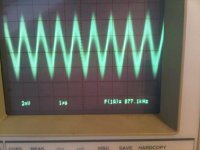
When taking AC measurements on the speaker output, I have a AC voltage of around 4mV with a frequency around 800 kHz as per the attached image.
I took this measurement in different conditions with no change:
- 1 pair of output transistor instead of 2
- Switching Q3 from a 2SC2911 to a BD139-16
- Swapping the capacitance multiplier to the voltage regulator
- Modifying the quiescent current
However, the following has an impact on the AC peak-to-peak (p-2-p) voltage of the measurement with modifying the frequency:
- Measuring at the speaker output using the chassis as a ground (the voltage moves to around 150 mV p-2-p)
- Moving a hand around the CCS and signal input part of the amplifier PCB (increases the voltage to around 50 mV p-2-p)
- Touching a heatsink with the hand reduces the voltage
I'm wondering what could cause such behavior and what I shall do to confirm and get rid of it provided it makes sense...
- Is the amp oscillating and what could cause this?
- Is the amp catching some RF ?
- ?
Looking forward to receiving any suggestion,
Jean-Francois.
Hi,
I'm quite a newbie in amp building and measurements and having looked at this thread with great interest I decided to revive it with my newbie questions...
I built a JLH-2005 mono-bloc based on Geoff's website and PCB from the following link:
JLH-2005 – NOTES
It is built with 2 pairs of MJ15003 for output transistors matched at a hfe around 70. For the power supply I built two set of PCBs, a capacitance multiplier or a voltage regulator. I'm presently using the cap multiplier.
I set-up the quiescent current at roughly 1,4 A per output transistor measured across the 0R1 resistors (Q1A=0,142V, Q1B=0,142V, Q2A=0,138V, Q2B=0,141V).
Voltages measured on the output transistors seems fine, with a Vbe ~ 0,8V.
When taking AC measurements on the speaker output, I have a AC voltage of around 4mV with a frequency around 800 kHz as per the attached image.
I took this measurement in different conditions with no change:
- 1 pair of output transistor instead of 2
- Switching Q3 from a 2SC2911 to a BD139-16
- Swapping the capacitance multiplier to the voltage regulator
- Modifying the quiescent current
However, the following has an impact on the AC peak-to-peak (p-2-p) voltage of the measurement with modifying the frequency:
- Measuring at the speaker output using the chassis as a ground (the voltage moves to around 150 mV p-2-p)
- Moving a hand around the CCS and signal input part of the amplifier PCB (increases the voltage to around 50 mV p-2-p)
- Touching a heatsink with the hand reduces the voltage
I'm wondering what could cause such behavior and what I shall do to confirm and get rid of it provided it makes sense...
- Is the amp oscillating and what could cause this?
- Is the amp catching some RF ?
- ?
Looking forward to receiving any suggestion,
Jean-Francois.
Attachments
Hi Jean-Francois,
It looks indeed either a low-level oscillation or some external influence.
Because it doesn't change with the changes you made, it most probably is external.
If you short the input of the amp, does it change?
If you disconnect the scope probe from the amp, and short the probe input to the probe ground lead, do you still see it?
jan
Jan,
Thanks for your prompt suggestions.
1) Shorting the amplifier signal input, the AC is still there but with a greatly reduced amplitude
2) I'm not sure I got your second suggestion right.
After measuring the signal, I remove the probe and the signal is still there on the screen. If I shortcut the probe, the AC disappears on the oscilloscope.
Regards,
Jean-Francois.
After measuring the signal, I remove the probe and the signal is still there on the screen. If I shortcut the probe, the AC disappears on the oscilloscope.
Regards,
Jean-Francois.
So if the probe is hanging in the air disconnected from the amp, only scope ground connected to amp ground, the oscillation is still there on the screen, but if you disconnect the scope probe ground from the amp ground, it's gone?
In that situation, does moving the probe away and closer to the amp do anything?
Are both the scope and the amp on the same mains outlet? Does it change when moving them to different outlets?
Is the amp grounded through a 3-prong outlet?
jan
Jan,
I tried to move the scope to another outlet without change.
The amp is grounded through a 3-prongs outlet.
The amp is also earthed internally using a star topology (I did not implement any ground loop breaker). The main earth is connected to the chassis, the chassis to the input signal RCA ground and the input signal RCA ground back to the earth star -I can draw a detailed diagram if you believe that the earthing scheme may be in cause).
I'm using a 10 ohm resistor at the speaker output for measurement purposes - I tried with and without a zobel network as well without any difference.
What's happening is a bit different from what I tried to explain - not easy to describe without being in front of the bench
Below some pictures of each measurement - in numeric mode on the oscilloscope. This should hopefully make the things clearer.
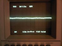
Step 1: Oscilloscope probe connected to the speaker sockets (both ground and probe)
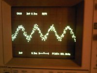
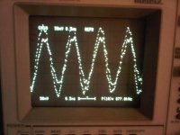
Step 2: Oscilloscope probe hanging in the air, ground still connected
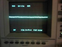
Step 3: Oscilloscope probe connected to the speaker socket - ground in the air
=> Please note that I have adjusted the range to 50 mV instead of 2 mV to enable the curve to stay on the screen
Step 4: Both probe and ground disconnected
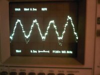
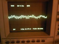
Step 5: Oscilloscope probe connected to the speaker socket - ground connected to the chassis
=> I adjusted again the range to 50 mV
Step 6: Oscilloscope probe connected to the speaker sockets (both ground and probe) + signal input shorted
=> In this last case, frequency of measurement is quite erratic - in the range of MHz.
I tried to move the scope to another outlet without change.
The amp is grounded through a 3-prongs outlet.
The amp is also earthed internally using a star topology (I did not implement any ground loop breaker). The main earth is connected to the chassis, the chassis to the input signal RCA ground and the input signal RCA ground back to the earth star -I can draw a detailed diagram if you believe that the earthing scheme may be in cause).
I'm using a 10 ohm resistor at the speaker output for measurement purposes - I tried with and without a zobel network as well without any difference.
What's happening is a bit different from what I tried to explain - not easy to describe without being in front of the bench
Below some pictures of each measurement - in numeric mode on the oscilloscope. This should hopefully make the things clearer.
Step 1: Oscilloscope probe connected to the speaker sockets (both ground and probe)
Step 2: Oscilloscope probe hanging in the air, ground still connected
Step 3: Oscilloscope probe connected to the speaker socket - ground in the air
=> Please note that I have adjusted the range to 50 mV instead of 2 mV to enable the curve to stay on the screen
Step 4: Both probe and ground disconnected
Step 5: Oscilloscope probe connected to the speaker socket - ground connected to the chassis
=> I adjusted again the range to 50 mV
Step 6: Oscilloscope probe connected to the speaker sockets (both ground and probe) + signal input shorted
=> In this last case, frequency of measurement is quite erratic - in the range of MHz.
Attachments
- Status
- This old topic is closed. If you want to reopen this topic, contact a moderator using the "Report Post" button.