Hey guys,
I scored an Eico 666 tube tester recently. I found info on it and replaced the 2 silicon diodes and capacitors. The unit seems to work fine, but I can't seem to get the "line adjust" to work. The meter only moves a little, and not even remotely close to the line mark. It did the same thing BEFORE I changed the diodes and caps, btw.
It does test tubes fine. It's NOT the meter. I have the schematic and it's so simple an idiot can follow it. Unfortunately I'm a moron, not an idiot. I checked the resistors, and pots in the line set circuit, and everything is within spec. I have found other eico's with the same problem on ebay, but they work fine in tube test. What the heck am I overlooking ???
Anyone here have some experience with these? I searched the net, but came up empty on this issue.
Thanks.
Marc
Hi Marc ( runco990 ) ,
According the book “ Tube Testers and Classic Electronic
Test Gear “ by Alan Douglas , Sonoran Publishing , 2000 ,
follow the following REPAIR TIPS :
EICO 666
“ If the line adjust doesn’t work , check the selenium rectifier
and the internal calibration pot , near it , and the electrolytic
capacitor . The “grid” pot is prone to burnout from testing
shorted tubes – pop the back cover off and look at the fibre
strip supporting the resistance element , near to the zero end . “
NOTE : Alan Douglas says : “ The 666 roll charts have an unusually high number of errors , or changes from one edition to the next . The charts are numbered up to 666-09 , and while errors were usually corrected in new editions , other typos appeared each time”
So , be careful !!!
I hope it helps the troubleshooting ,
Regards ,
Carlos
I did change the SELENIUM (not silicon, silly me) diodes and the 2 capacitors. I'll dig into the pots next.
I read about the rollchart errors... scary. The tester did come complete with manual, schematic, and rollchart supplement. It also came with a 50 cent copy of Do-it yourself TV trouble-shooters guide. (1957)
COOOL!!
I'll check the pots, though the meter suggests they were OK.
Marc
I read about the rollchart errors... scary. The tester did come complete with manual, schematic, and rollchart supplement. It also came with a 50 cent copy of Do-it yourself TV trouble-shooters guide. (1957)
COOOL!!
I'll check the pots, though the meter suggests they were OK.
Marc
Hi Marc ,
Do it . Pay attention to the pots , may be a cracked track ,
may be a bad contact sliding cursor , may be one ( or more )
loose terminal (s) , may be a “cold” soldering , etc . Test it
COLD , and HOT ( you can use a hair drier to raise its
temperature ) .
Good luck !! And don’t forget ..... read the paper Do It
Yourself TV Troubleshooter , from the beginning to the end ,
after all , it costs half dollar , and 1957 is my birth year .
Best Regards ,
Carlos
Gentlemen, it seems I do indeed need a replacement meter for my Eico 666.  Does anyone have a spare they can possibly part with? The winding is burned.
No, I do not have the skill to re-wind a meter movement..... just in case someone suggests this. I know some of you blow your own tube glass, but that's a little advanced for me. LOL!
Does anyone have a spare they can possibly part with? The winding is burned. No, I do not have the skill to re-wind a meter movement..... just in case someone suggests this. I know some of you blow your own tube glass,
but that's a little advanced for me. LOL!Hi Marc ,
The EICO model 666 , has a 200 uA ( 200 microampere )
X 1000 ohms , meter movement coil .
With this precious data and living in L.A. ( a big , big city ),
as you are , it is not hard to find ( I would say very easy to
find ) an specialist in rewinding D’Arsonval coil meter
movement . You need only to get informations about it ,
on specialized electronics workshops , or perhaps to try
the “ yellow pages” .
In Sao Paulo ( where I live ) , smaller than L.A. , we have
three workshops of these specialized professionals .
Usually they are old people with A LOT of experience and
a DOUBLE LOT of patience .
In my point of view , this is the better solution , because
only the meter movement , is very , very hard to find , and
if you could get one , perhaps it would be in bad shape than
yours .
Good luck ,
Carlos
666 - the devil made me do it
Find someone to rewind it - or:
You could repurpose another meter to work in the 666, although this is rather tedious. I haven’t done this myself, but I observed a friend pull this off so well that you could hardly tell the fake from the original (not a 666 though). You find another meter of the right size that fits properly into the 666 space with a 200uA movement. You can use a more sensitive movement and “pad it down”, but hopefully that won’t be necessary. There are new meters available in a broad range of sizes, although you might find a surplus meter that fits if you’re lucky. You disassemble the old, broken 666 meter. Carefully remove the back plate with the scale markings printed on it. This is usually a thin aluminum plate with two screws holding it in place. After removing any dust, you place this back plate into a scanner, and run a high-resolution color scan, saving it as a bit-map or some other uncompressed file. Now disassemble the new meter. The new meter will either be blank (unlikely) or will have its original and now irrelevant markings. You are going to cover up this old scale with a new scale. You will print out a color print image of the 666 scale on photo paper or some other sturdy stock, maybe even a plastic sheet, and you will use an adhesive to glue the new scale onto the new meter’s back plate. If the stock is very stiff, you might even remove the back plate altogether and just insert the new scale. Be careful not to bend or to torque the pointer. Turn off ceiling fans as these often are enough to make the pointers move about. You may have to use a photo editor application to adjust the size and placement of the scales for your new meter, noting where full scale and zero scale are on the new meter versus the old. Also, you’ll want to clean up blemishes and make the color and contrast right. All lines need to converge on the bearing point of course. Maybe try some black and white trials runs first. It may also be possible to just use the old back plate with the new meter, with perhaps a bit of snipping. There is never much clearance between the pointer and the back plate, so you will probably have to remove the unused plate.
If you're determined, you can can exorcise the 666.
Marc ,
The Idea is excellent under the “cosmetic” point of view ,
BUT , you can not forget that the INTERNAL RESISTANCE
of the meter movement coil is VERY IMPORTANT ,
because it is part of the entire circuit , and it is in the
measured signal path .
You can use any kind of 200 uA meter , if the meter
circuit has a signal amplifier , BUT the EICO 666 , does
not have one .
If you ignore it , the shunts , the calibration and all the
rest of the circuit will not work properly .
Carlos

Of course Carlos’ point is valid. You would need to find a 200uA/ 1Kohm meter, or a less-than-1Kohm meter to which you’d add a series matching resistor. There are three common standard full-scale native current values for analog meter movements: 50, 100 and 200uA. With a combination of shunt and series resistance, a more sensitive meter can probably be made to work. You might want to use pots to adjust the meter in to match the circuit. As I said, none of this is necessarily easy. Is all this sounding too hard? For me, it would not be worth it. I checked eBay and 666’s are selling like the devil (sorry, the devil made me do it) for between $75 and $150. I might pop for one of those, make one clean working unit out of the two, and have spare parts unit left over (I've used that excuse a lot and I have pairs of several units, like Noah's Ark for old electronics). Or, you could spend a lot more for a better Hickok. Depends how much you love the little devil.
refference said:Marc ,
The Idea is excellent under the “cosmetic” point of view ,
BUT , you can not forget that the INTERNAL RESISTANCE
of the meter movement coil is VERY IMPORTANT ,
because it is part of the entire circuit , and it is in the
measured signal path .
You can use any kind of 200 uA meter , if the meter
circuit has a signal amplifier , BUT the EICO 666 , does
not have one .
If you ignore it , the shunts , the calibration and all the
rest of the circuit will not work properly .
Carlos
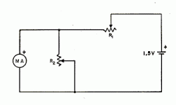
Anyone who needs the "how to" of measuring a meter's internal resistance see the attached. R1 should be sufficiently large to allow full scale deflection. Thus if you have a 100 uA meter and 1.5V battery at least 25k -- and make sure the darn thing is set for max resistance when you hook it up ! R2 should be about 1K
Set up the circuit without R2 inserted. Adjust R1 for full scale deflection. Insert R2 and adjust to 1/2 scale reading. Remove R2 and measure -- this is the internal resistance.
Attachments
I suppose you could also do this with only a large series resistor, R1. Starting from the high resistance side, gradually lower the pot’s resistance until full-scale deflection is observed. With a DMM, measure the voltage across R1. Then measure the voltage across the meter. Disconnect the meter and the battery, and measure the resistance of R1 without disturbing its setting. The voltage across R1 divided by the measured resistance of R1 gives you the full-scale current. The voltage across the meter at full-scale divided by this current gives the meter resistance. This might be the more accurate approach since mid-scale deflection is not always linear, and the two-resistor approach requires that R1>>R2 for R2 to approximate the meter resistance. You might need a larger voltage source in that case. As others have said, please be careful; these movements ARE fragile. The back-to-back diode suggestion is a good one. At full-scale, an exact replacement meter (200uA/1000 ohms) would see only 0.2 volts across the meter terminals full-scale, not enough for the diodes to begin to conduct and distort the readings.
Quick back-of-the-napkin analysis: If you’re measuring a 200uA/1000 ohm meter with the two-resistor approach and only 1.5 volts, R1 will be adjusted to 6500 ohms to give 200uA full-scale, and then R2 will have to be adjusted to about 866 ohms to give a half-scale reading on the meter. You’d conclude that the meter must have an 866 ohm winding, when in fact it’s really 1000 ohms, and error of 13%. R1 must be a lot larger than 6500 ohms so that it more closely approximates a 200uA current source as far as the meter resistance is concerned. I think the single resistor approach is easier and allows the use of a safe small voltage like a 1.5 V cell.
Morgan Jones has a write-up in his BVA on testing meters. Similar to what Brian describes - but I don't remember exactly. MJ does spec a 9V battery, which I think is a no no. 1.5V usually does the trick.
Also check the back of the meter, and see if there is a diode already strapped across the meter terminals. You sometime see them on old equipment factory installed or by a wise old man. They can fail short if someone or something gives the meter too much juice. Symptom is a dead meter, as all the current runs through the shorted diode rather than the meter.
Just to be clear, you run two diodes parallel in opposite directions in parallel with the meter. Not perfect protection, but it is very cheap insurance. You can peg the meter hard for a few more seconds before destruction. Under most conditions, it will not affect your accuracy - which was probably not all that great factory fresh.
--------->|-------
<-----meter------->
---------|<--------
- Status
- This old topic is closed. If you want to reopen this topic, contact a moderator using the "Report Post" button.
- Home
- Design & Build
- Equipment & Tools
- Eico 666 (satan's choice) tube tester help.