Thank you for carrying out the thankless task of debugging the schematic and converting it to a working PCB, readily useable by all DIYaudio members.Elvee, thank you very much for sharing this!
I now realize that I made another mistake, fortunately one that doesn't require schematic or PCB revisions: the frequency adjustments do not cover the intended range. I somewhat overlooked the fact that there are 4 frequency-defining components for each filter frequency, meaning that the variation of a single resistor with the trimmer only results in a square-root variation of the frequency.
Currently, the 1Meg + 100K variable only covers ~half of the intended variation range.
There are two possible solutions: use 2% capacitors for the filters or keep the 5% and increase the range by changing the 1Meg fixed to 910K and the trimmer for a 220K.
Even more radical, you could use 820K fixed + 470K variable, but I like to keep the trimmer as small as possible, as it is a weak point, especially being used in variable resistor mode.
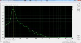
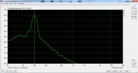
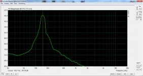
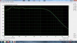
I note that your frequency graphs show a marginally low center frequency.
This could be corrected by reducing R56 and similar resistors. You should be able to gain 1 or 2dB and center your trimmers by reducing it by ~10% (next lower E24 value).
Regarding the pinout of the BF245 vs. 256, the original Philips datasheet shows identical pinouts.
Motorola and others seem to have departed from it, but in reality it does not matter: these FETs are symetrical, and the tiny differences, if present, would only affect the VHF/UHF performance. They are completely irrelevant for AF applications. Just orient the flat side according to the maker, much like when you replace a 2N3904 with a BC547.
A note for our friends on the other side of the pond: to convert the HumBoy to a 60Hz system, you just need to decrease all the filter capacitors by 20%, conveniently meaning the next lower E12 value: for example, 220nF would become 180nF
Last edited:
Here is the (provisionally?) final version of the schematic:
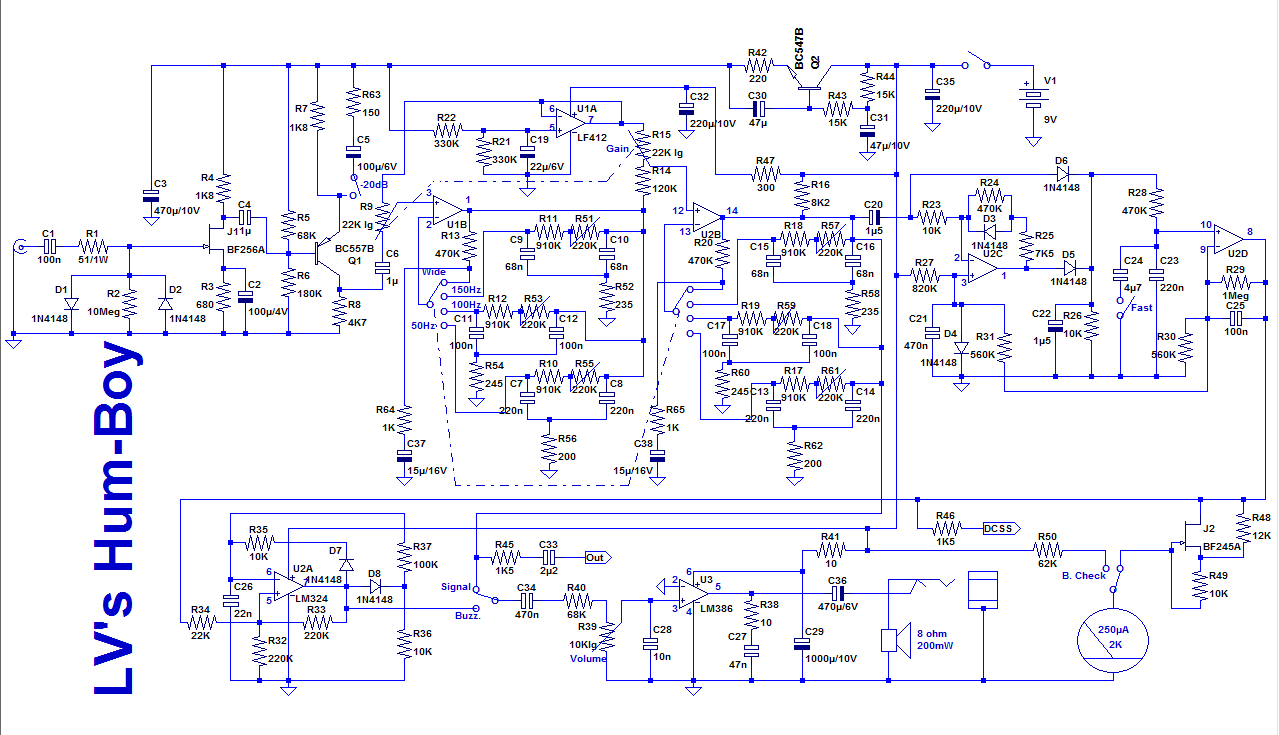
Important note:
I also noticed that C5 had been drawn upside down. This update shows C5 correctly oriented
Here are some guidelines for using the DCSS output and the slow-response mode.
The main use of the HumBoy is as a sniffer, to quickly locate the source of a perturbation, but when you want to assess objectively the effect of a change on a design, for example the addition of a shield, or a different orientation of a transformer, you can stick the probe to the DUT, with double-sided adhesive tape for example, connect a voltmeter to the DCSS output, adjust the gain to read 2V and test various configurations, always leaving all the rest unchanged.
You first test each change individually, and when you have found the best option(s), you can begin to mix the most promising ones to incrementally improve the hum rejection until you reach the best configuration possible.
The averaging afforded by the slow mode allows you to accurately estimate the values, even when you work at the S/N limit.
Attachments
... keep the 5% and increase the range by changing the 1Meg fixed to 910K and the trimmer for a 220K.
...
I note that your frequency graphs show a marginally low center frequency.
This could be corrected by reducing R56 and similar resistors. You should be able to gain 1 or 2dB and center your trimmers by reducing it by ~10% (next lower E24 value).
All done and very much worth it! It is now very easy to center the trimmers. I was able to calibrate it even using my sound card. 50Hz seems just a bit off but it works fine I think.
Attachments
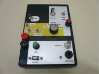
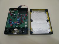
 Panel layout inevitably is all over the place so I tried to save it with some artwork. But it is what it can do that makes it indispensable.
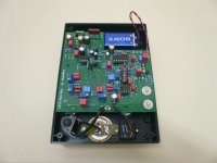
This is what I'm working on currently. It seems that an aluminum foil on the rear is all that it needs. I'll post results. Funny thing is that without shield it is sensitive at the top side and almost not at all at the components side bellow. But when a shield is added it helps a lot at the top.
I settled to this. Although not a Faraday cage it works well together with the pcb. There will be some buzzing proportional to gain setting but it's not affected by hand proximity at all and allows plenty of headroom for the probes to sniff around noisy sources.
Attachments
Good.
Be aware that the Humboy has a lot of excess gain built-in: even in a completely closed metallic case, with the input shorted, you will get a response if you push the gain near the max., due to internal noise
The excess gain is to make sure that you can always use the maximum sensitivity, even with ineffective probe types.
It easy to dial back the gain if necessary, but if gain is lacking, there is no easy way to push it up.
The architecture also results in a large gain: the BPF's need a large gain to achieve a sharp selectivity, and a front-end with gain is also necessary to optimize the S/N figure.
Some of the gain is thrown away with R14, but you can adopt a higher value if you think the current gain is still too high.
A word or two about using the Humboy:
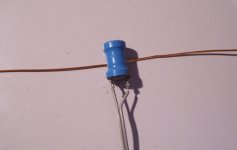
When you use the inductive probe, which will normally be the case in most situations, you have to be aware that due to the laws of induction, the optimal orientation wrt. the current to detect can be counterintuitive.
This is illustrated in this pic, with the coil and wire naked, for more clarity:
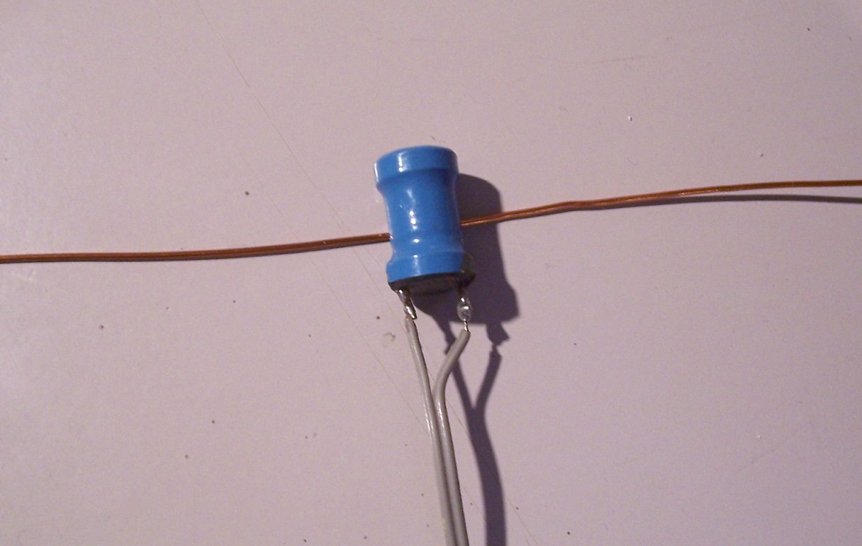
This configuration will result in the highest sensitivity, in the case of a single, isolated current: the current direction is normal wrt. the axis of the coil; or in another words, the current needs to be tangential to the coil, and that remains valid at any distance.
That is the type of situation you will encounter if you want to detect the ground-loop current in the shield of a cable.
With a power cable, like a figure-of-8 type, the two currents cancel one another, and at a distance, you will detect nothing, but in close proximity of one of the conductor, the asymmetry will create a small, but detectable field
When the current/field situation is more complex, things may vary: with a cored component like a transformer or choke, the field lines will often be normal to the iron surface, meaning that you will often get the highest response when you point the probe towards the source.
With multipole, multiphase field configuration, the situation can also vary: for example, if you try to detect the field generated by a EHV power from a long distance (hundreds of meters or more), pointing the probe towards the source will generally yield the best sensitivity.
Another important thing to keep in mind: when you use the Humboy to trace the source of hum, remain open-minded. Leave no stone unturned, even the least promising ones. If you have preconceptions about the perturbation, you might miss its true origin.
If you need to resort to a tool like the Humboy to solve a problem, it means that its origin can be completely unexpected and difficult to trace: earlier in the thread I showed an example where the metallic frame of the case conducted and transported the hum far away from its original source, the transformer.
This is just one example, and you may be confronted with other weird, unheard-of situations.
The Humboy makes the exploration of a device quick, easy and intuitive: use that at your advantage, explore everything, each cubic inch, each part, each cable, etc.
You may find more than one hot-spots, and need to sort them out to determine which one(s) is the true, problematic one, but don't limit yourself, don't neglect anything.
Also make the test for both the electrostatic and magnetic cases: you never know a priori which one causes your troubles, even if you have some prior ideas.
Be aware that the Humboy has a lot of excess gain built-in: even in a completely closed metallic case, with the input shorted, you will get a response if you push the gain near the max., due to internal noise
The excess gain is to make sure that you can always use the maximum sensitivity, even with ineffective probe types.
It easy to dial back the gain if necessary, but if gain is lacking, there is no easy way to push it up.
The architecture also results in a large gain: the BPF's need a large gain to achieve a sharp selectivity, and a front-end with gain is also necessary to optimize the S/N figure.
Some of the gain is thrown away with R14, but you can adopt a higher value if you think the current gain is still too high.
A word or two about using the Humboy:
When you use the inductive probe, which will normally be the case in most situations, you have to be aware that due to the laws of induction, the optimal orientation wrt. the current to detect can be counterintuitive.
This is illustrated in this pic, with the coil and wire naked, for more clarity:
This configuration will result in the highest sensitivity, in the case of a single, isolated current: the current direction is normal wrt. the axis of the coil; or in another words, the current needs to be tangential to the coil, and that remains valid at any distance.
That is the type of situation you will encounter if you want to detect the ground-loop current in the shield of a cable.
With a power cable, like a figure-of-8 type, the two currents cancel one another, and at a distance, you will detect nothing, but in close proximity of one of the conductor, the asymmetry will create a small, but detectable field
When the current/field situation is more complex, things may vary: with a cored component like a transformer or choke, the field lines will often be normal to the iron surface, meaning that you will often get the highest response when you point the probe towards the source.
With multipole, multiphase field configuration, the situation can also vary: for example, if you try to detect the field generated by a EHV power from a long distance (hundreds of meters or more), pointing the probe towards the source will generally yield the best sensitivity.
Another important thing to keep in mind: when you use the Humboy to trace the source of hum, remain open-minded. Leave no stone unturned, even the least promising ones. If you have preconceptions about the perturbation, you might miss its true origin.
If you need to resort to a tool like the Humboy to solve a problem, it means that its origin can be completely unexpected and difficult to trace: earlier in the thread I showed an example where the metallic frame of the case conducted and transported the hum far away from its original source, the transformer.
This is just one example, and you may be confronted with other weird, unheard-of situations.
The Humboy makes the exploration of a device quick, easy and intuitive: use that at your advantage, explore everything, each cubic inch, each part, each cable, etc.
You may find more than one hot-spots, and need to sort them out to determine which one(s) is the true, problematic one, but don't limit yourself, don't neglect anything.
Also make the test for both the electrostatic and magnetic cases: you never know a priori which one causes your troubles, even if you have some prior ideas.
Attachments
If I understand correctly, you want pdf files for top and bottom copper layers to make your own pcb? I'm not sure how to do this from the gerber files, those are for ordering to pcb manufacturers. I'll see if I can extract a pdf from the diptrace file otherwise I could upload this but you will need to install the program to open it and print.
- Home
- Design & Build
- Equipment & Tools
- An effective weapon for your hum problems: the HumBoy