Hi there
Hum is one of the most frequent problems encountered by DIYers (and professionals!).
Here is a tool specifically designed to detect, identify, track and locate all types of hum: electrostatic and magnetic coupling, ripple, ground issues, etc.
In principle, the basic equipment of a normal lab or workshop is sufficient to do the job: a signal-tracer or lab-amplifier coupled to an improvised E-mode or H-mode probe for example.
However, a dedicated tool is very useful, especially for difficult cases.
The HumBoy can work as a basic signal-tracer, but it also has special features: one is the very high gain available (insane in fact, literally) and the other is the very high frequency selectivity: it includes three very narrow bandpass filters centered on 50Hz, 100Hz and 150Hz.
The reason for the 50Hz (or 60Hz) is obvious: it is the mains frequency, and basic hum problems are caused by this frequency leaking into circuits through electrostatic or magnetic coupling.
The 100Hz (or 120Hz) has a different origin: it is caused by the rectification process in a supply, and appears in the ripple voltage and the currents around the filter caps and the ground.
The 150Hz is the third harmonic, and is always present to some degree in the mains spectrum because of the waveform distortion, but when a transformer begins to saturate, some of the flux leaks out of the magnetic circuit, and these leaks consist mainly of odd harmonics, primarily third.
When hum appears in an audio chain, it can be a mix of different types, having different origins. You may be able to detect the fundamental by hear, but the ability to discriminate and track each frequency can help in locating quickly the origin(s) of the problem.
Finally, the HumBoy includes a detector coupled to a V-F converter, because the hum frequencies aren't within the optimum sensitivity range of the human ear, and its logarithmic response to the amplitude doesn't help either.
By contrast, the ear is extremely sensitive to small pitch changes, helping to direct the search and quickly locate the source, and hopefully the culprit.
Its input can cope with different types of probes: direct, magnetic or electrostatic.
In the direct mode, it can be connected to a supply voltage, to detect residues of ripple for example.
The magnetic probe (typically a small drum-core choke) sniffs magnetic leaks from magnetic components or AC currents in a wire.
The electrostatic probe (typically a small pigtail left bare at the end of a coaxial cable) identifies unwanted capacitive couplings.
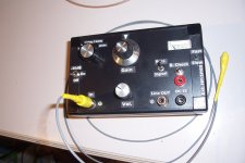
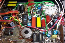
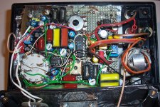
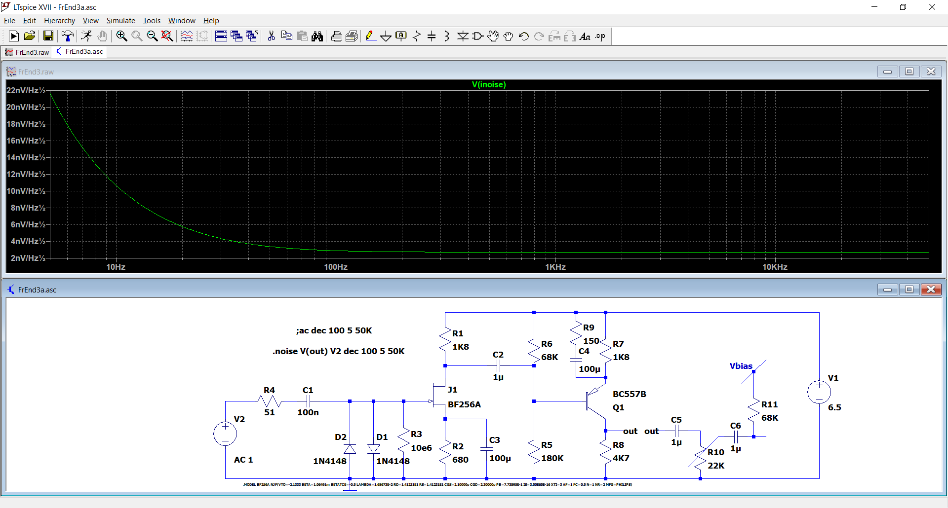
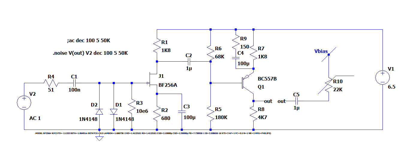
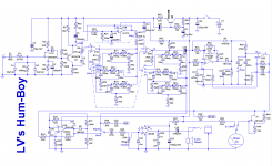
This is the circuit: it is just plain old analogue technology, nothing especially smart or fancy.
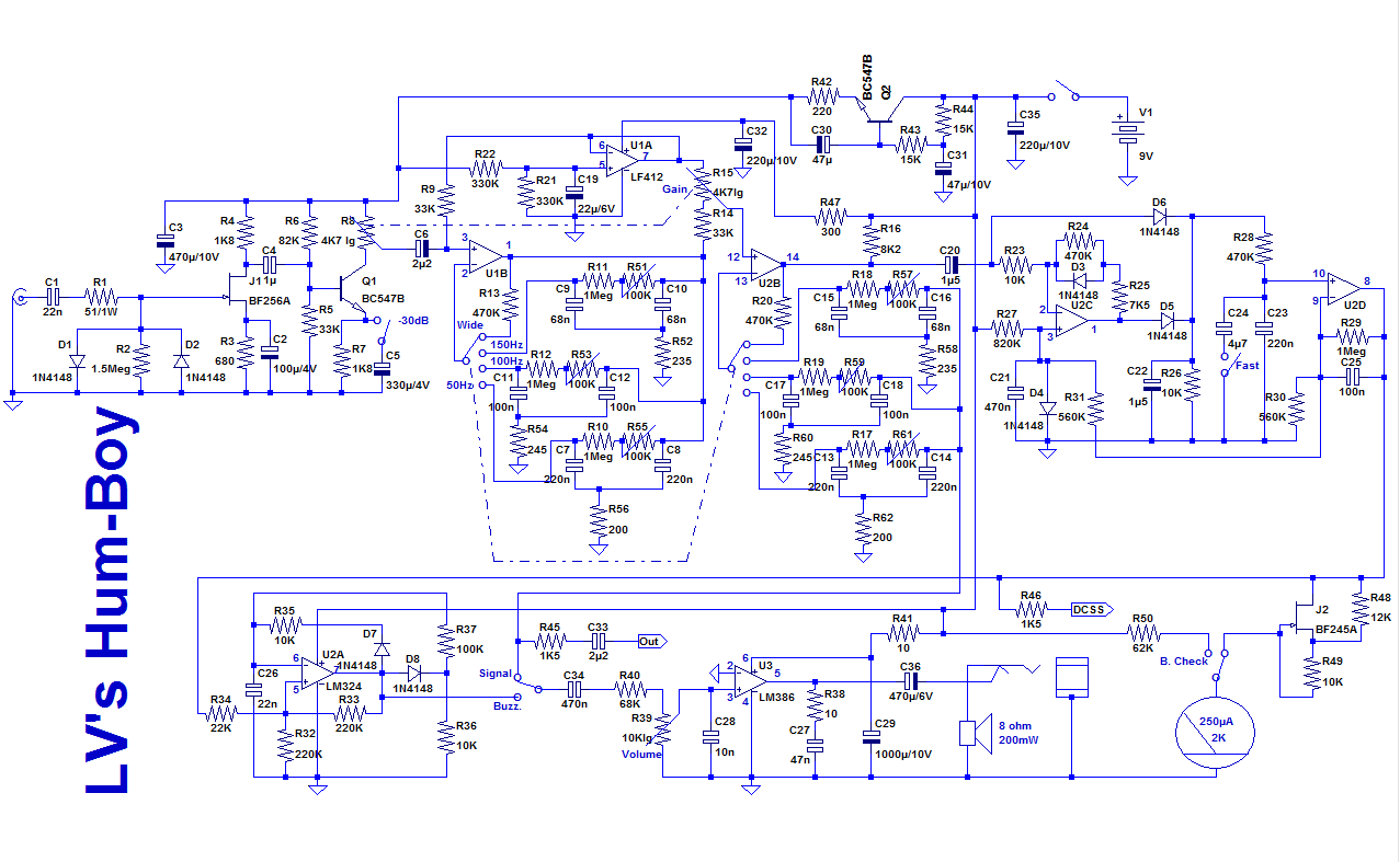
This is the finished tester:
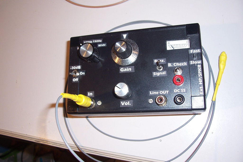
I have included all possible bells and whistles.
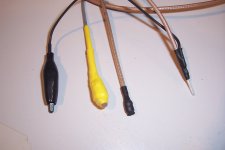
These are examples of probes:
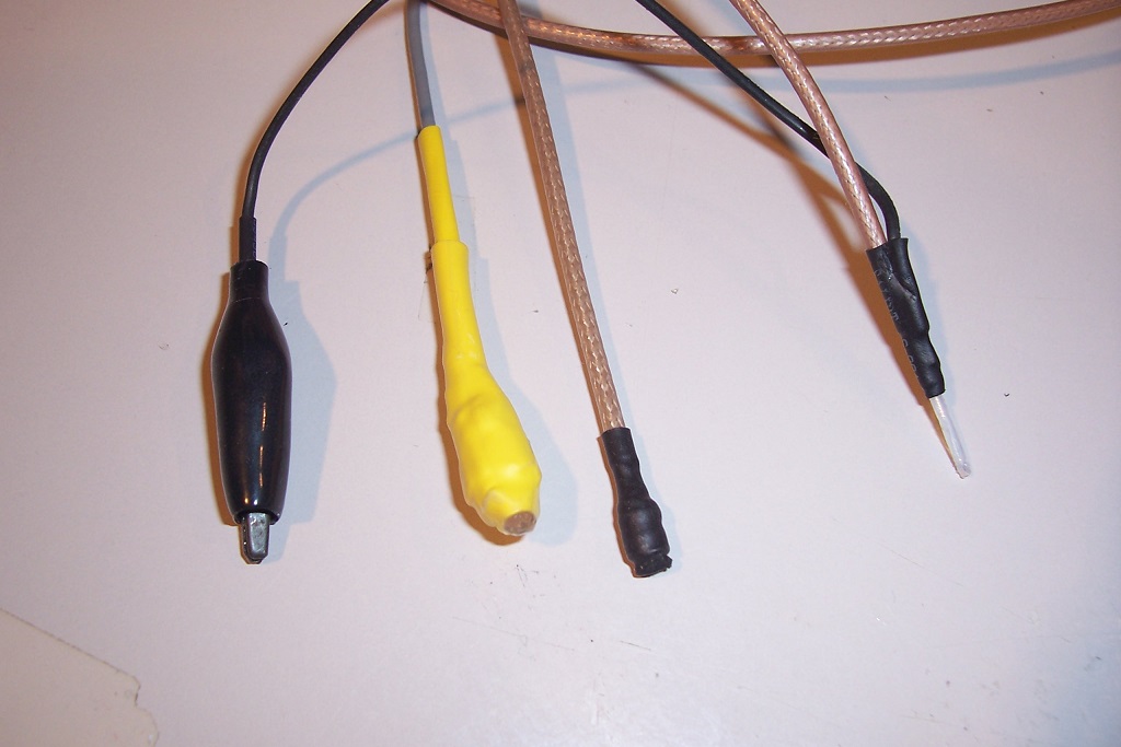
The yellow one is the general-purpose magnetic sensor: a 10mH choke, electrostatically shielded.
The black one is the miniature magnetic sensor, capable of locating a single wire in a bundle.
This pic shows its construction: it is made by winding a large number of turns of 0.03mm enameled wire around the center conductor of a miniature coaxial cable.
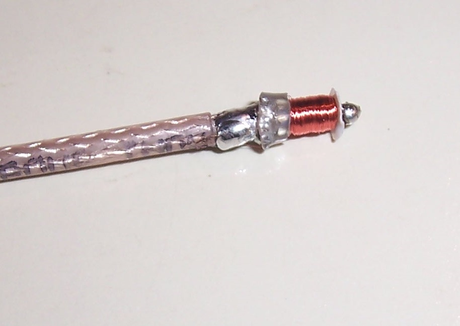
The inner conductor is made of steel, thus magnetic, and acts as the core of the inductor.
The inductance is 600µH and the resistance 50 ohm.
The last one is the E-type probe, also capable of accurately pinpointing a source.
The sensitivity is absolutely insane: in simple, audio-tracer mode, it is capable of eaves-dropping the audio from a regular telephone pair, without contact just by magnetic induction.
In bandpass mode, it is capable of detecting the 50Hz magnetic field generated by a 110kV HV power line from a distance of ~1 mile.
Hum is one of the most frequent problems encountered by DIYers (and professionals!).
Here is a tool specifically designed to detect, identify, track and locate all types of hum: electrostatic and magnetic coupling, ripple, ground issues, etc.
In principle, the basic equipment of a normal lab or workshop is sufficient to do the job: a signal-tracer or lab-amplifier coupled to an improvised E-mode or H-mode probe for example.
However, a dedicated tool is very useful, especially for difficult cases.
The HumBoy can work as a basic signal-tracer, but it also has special features: one is the very high gain available (insane in fact, literally) and the other is the very high frequency selectivity: it includes three very narrow bandpass filters centered on 50Hz, 100Hz and 150Hz.
The reason for the 50Hz (or 60Hz) is obvious: it is the mains frequency, and basic hum problems are caused by this frequency leaking into circuits through electrostatic or magnetic coupling.
The 100Hz (or 120Hz) has a different origin: it is caused by the rectification process in a supply, and appears in the ripple voltage and the currents around the filter caps and the ground.
The 150Hz is the third harmonic, and is always present to some degree in the mains spectrum because of the waveform distortion, but when a transformer begins to saturate, some of the flux leaks out of the magnetic circuit, and these leaks consist mainly of odd harmonics, primarily third.
When hum appears in an audio chain, it can be a mix of different types, having different origins. You may be able to detect the fundamental by hear, but the ability to discriminate and track each frequency can help in locating quickly the origin(s) of the problem.
Finally, the HumBoy includes a detector coupled to a V-F converter, because the hum frequencies aren't within the optimum sensitivity range of the human ear, and its logarithmic response to the amplitude doesn't help either.
By contrast, the ear is extremely sensitive to small pitch changes, helping to direct the search and quickly locate the source, and hopefully the culprit.
Its input can cope with different types of probes: direct, magnetic or electrostatic.
In the direct mode, it can be connected to a supply voltage, to detect residues of ripple for example.
The magnetic probe (typically a small drum-core choke) sniffs magnetic leaks from magnetic components or AC currents in a wire.
The electrostatic probe (typically a small pigtail left bare at the end of a coaxial cable) identifies unwanted capacitive couplings.
This is the circuit: it is just plain old analogue technology, nothing especially smart or fancy.
This is the finished tester:
I have included all possible bells and whistles.
These are examples of probes:
The yellow one is the general-purpose magnetic sensor: a 10mH choke, electrostatically shielded.
The black one is the miniature magnetic sensor, capable of locating a single wire in a bundle.
This pic shows its construction: it is made by winding a large number of turns of 0.03mm enameled wire around the center conductor of a miniature coaxial cable.
The inner conductor is made of steel, thus magnetic, and acts as the core of the inductor.
The inductance is 600µH and the resistance 50 ohm.
The last one is the E-type probe, also capable of accurately pinpointing a source.
The sensitivity is absolutely insane: in simple, audio-tracer mode, it is capable of eaves-dropping the audio from a regular telephone pair, without contact just by magnetic induction.
In bandpass mode, it is capable of detecting the 50Hz magnetic field generated by a 110kV HV power line from a distance of ~1 mile.
Attachments


A 2N3819, MPF102 some selections of BC264 (probably B).Hello Elve,
could you please give us replacement type for BF245?
JP
Not really critical, and it would be possible to dispense with it: its role is just to make the response of the meter non-linear, to better appreciate small levels, but it is just accessory, and a simple resistor could replace the FET and resistors around it.
It is just icing on the cake, but I will discuss it in more details later.
Sure you can: with a spectrum display and FFT configured for high resolution and long averaging times, you could get an excellent resolution, and see the 50, 100, 150Hz and also other harmonics.Very thoughtful as always! I was wondering if these probes would work with a sound card and PC distortion analyzer.
A PC has two main disadvantages: it will often be connected to the mains, or at least have relatively noisy PSU systems inside, and it will not natively convert the amplitude of a particular spectral line into a variable pitch output, but someone having basic programmation skills could easily do it.
The HumBoy is exclusively battery operated, and doesn't include any converter or switching device for quietness reasons.
The HumBoy is rudimentary and low-tech, but it has two main strengths:
One is the good frequency selectivity, and the other is the intuitive strength/pitch converter, allowing you to zeroing in on the interference source in seconds just by waving the probe in the region of interest (without having to look at a screen or instrument).
The frequency selectivity eliminates sources that are spurious (for the moment anyway), allowing you to concentrate on your current problem, but it also drastically reduces the noise bandwidth, allowing sensitivity levels unattainable by other means.
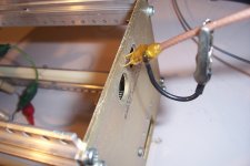
To illustrate the use of the HumBoy, here is an hypothetical example (but rooted in reality).
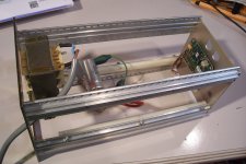
Imagine an elongated equipment chassis, with a small mains transformer at the rear, close to the mains entry:
If you have to lodge a sensitive equipment (RIAA or Mic preamp for example) in the chassis, you will logically place it in front, at the opposite end, as far as possible from the PT.
If you try this, you will be confronted with huge and intractable hum problems.
Surprising?
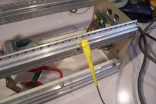
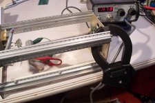
Well, not really: place a sensitive AC clamp ammeter on one of the aluminum profiles, and you will see a whopping 470mA current flowing through that part of the chassis:
The transformer is an old, 220V type, with little margin for 230V operation, and as a result it leaks stray field.
The loop configuration of the chassis can carry the resulting current over any distance, meaning the small board tied to the front panel will be affected by severe hum, no matter how far you place it, or the layers of Mumetal you interpose: the current will flow anyway.
Placing a Mumetal screen around the transformer itself would reduce the problem, but not eliminate it.
The sensible solution is to change the configuration, to eliminate the circulating current: it is much more effective, and the cost is zero.
It will effectively cure the problem (except for the HumBoy which will still be able to detect something, but it is designed for that, unlike your preamp)
Of course, you may not have a sensitive clampmeter available, you may not think of using one, and even if you want to, it won't be possible once the chassis is populated with boards, bulky components, wire bundles and side panels.
However, the HumBoy will be able to sniff the current flowing through the profiles from the outside:
You will also the 150Hz signature, something the clampmeter cannot do unless its line out is connected to a SA.
Sometimes, it may not even be possible to get near the profiles, because the chassis is inserted in a rack for example.
This is not a problem for the HumBoy: you can press this type of probe (basically two spikes making contact) directly against the chassis:
The circulating currents drop a tiny voltage across the few mm of aluminum, and the HumBoy in selective mode can detect and register this sub-nV voltage.
With the pinpointing probe, you can investigate internal perturbation sources.
In this location, you will detect a huge 100Hz signal:
Here, the 100Hz will have practically disappeared, but you will see a large
50/150Hz signal:
Attachments
No, not critical at all, but since the input handles nV levels, it has to remain at a reasonable distance of higher level circuits, downstream: the second filter bank, the V-F converter, and of course the audio PA.Great work! I have to try this. Is pcb layout critical, more than the usual precautions?
Extreme, paranoiac shielding is essential: you want to recover the signal from the probe only, and from nowhere else.
Anywhere in a lab or even in a house there are 50Hz fields, and if the shield has any gap or weakness, these fields will infiltrate the sensitive parts of the circuit and cause false readings.
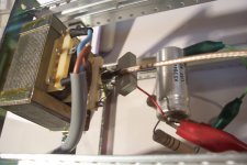
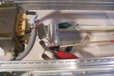
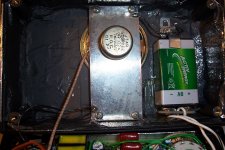
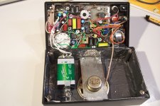
This is the inside of the tester:
As you can see, the whole plastic case is lined with adhesive aluminum, reinforced by graphite paint and numerous grounding leafs.
Even the cable to the speaker is a small coaxial, as it could radiate signal back to the input stage.
In fact, anything carrying a signal is shielded, like the cable to the sensitivity switch
Otherwise, you can see that the construction is rather sloppy
 , but this doesn't impair the operation:
Most of the components are non-critical: I have used PP and polycarbonate caps for the filter banks, but that's mostly to ensure a good temperature stability.
Mylar also works, but if you use the tester at temperatures widely different from that of the calibration, the filters will be slightly off-frequency.
The input opamp is a LF412. Initially, I had used a LM358 (it also works), but I found the TLO72 and LF412 quieter, and capable of operating perfectly down to 6V, even though they aren't supposed to.
Attachments
Currently, it looks like this. Less than 120x120 mm together with room for the battery. It's following the schematic markings. There will be a solid ground plane on the bottom layer. I'm trying to leave only the speaker and the panel meter off board. But it all depends on the box so final dimensions and layout could be adjusted. Generic rotary and toggle switches. Not sure about the later. It should be pcb mount vertical. I could just provide big pads to fit whatever available. I need to think about I/O connectors too. BTW, what is DCSS and what is the "Fast" switch for?
Capacitors' pitch is 5,08 mm for the small plastic and 2,5 mm for the electrolytics. But I see that Elvee has used much bigger. Are they for high voltage possibly to protect when the direct probe is used?
All suggestions are welcome.
Capacitors' pitch is 5,08 mm for the small plastic and 2,5 mm for the electrolytics. But I see that Elvee has used much bigger. Are they for high voltage possibly to protect when the direct probe is used?
All suggestions are welcome.
Attachments
Fast and excellent work.
If you find toggle switches fitting the height of other components and the rotary, to arrive at a flush front-panel, that's OK.
I have opted for PCB-mounted RCA receptacles, but if you prefer a different type (BNC ?), why not.
DC Signal Strength allows the connection of an external meter, to be able to compare accurately two situations.
Both the the internal meter and the DCSS are optional: the main operation method is based on the buzzing sound as a cue when you search for perturbation source.
The fast/ slow switch allows a longer averaging, to compare two situations very close to the noise floor.
You can leave it in the fast mode all the time, and spare a switch.
As I said, I went overboard and implemented all possible bells and whistles, but that might not be necessary. Feel free to prune out moderately useful or useless features.
Use modern capacitors: some of mine are NOS, 40/50 years old, but there is no need to make a steampunk instrument.
Only the input cap should have a reasonable voltage rating, to withstand inevitable mishaps.
100V for semiconductor circuits, more if you intend to use it on tube circuits.
In the meantime, I have had some afterthoughts to improve and streamline the front-end circuit:
The first mod is to increase the input cap to 100nF, and the input resistor to 10Meg. No PCB alterations required, and no bad surprise possible.
The second mod rationalize the amplification chain by using a PNP instead of a NPN: its input is Vcc-referenced, as is the FET output, and its output is GND-referenced, as is the filter output. The result is a much better PSRR.
It could even allow the elimination of the super-gyrator supply cleaner, but let's not take such a risk: it costs a simple transistor.
PCB alterations required, not tested, but 99% chances it works as intended.
The gain increasing network is now R9/C4. It allows 20dB increase, but could remain permanently in service, sparing another switch.
If you feel the need to investigate high-level perturbations, it could be retained.
The final mod avoids passing DC current into the gain potentiometer: this causes two possible issues: an increased noise level, because the track resistance is non-ideal and generates excess noise when DC-biased, and a strong output each time you touch the gain, because of the DC shift and the noise created by the DC bias.
I am not going to implement these mods on my build, except the input resistor and capacitor: it would be too complicated and messy, but other builders could benefit from a gain in performance, usability and a noise floor 14dB lower
Attachments
Lately I find myself enjoying pcb design very much! I guess I'm having my "armchair diy" period. Thanks for all clarification. I'll include the new mods but first I need to put them on the original schematic to be sure I understand correctly.
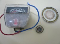
The rotary switch leaves about 15 mm clearance and I think vertical BNC will do. That is if I find any... Speaking about vintage components, I would like to use a couple. The first is a panel meter from an old portable cassette player that measures 440 ohm. For the speaker I have a few like the one you used but I'm curious to see if any of these in the picture would work. The very small one is from an old cellphone measuring 17,5 ohm and the disc is a piezo from an old digital wrist watch. Thoughts for saving space.
Thanks for all clarification. I'll include the new mods but first I need to put them on the original schematic to be sure I understand correctly. The rotary switch leaves about 15 mm clearance and I think vertical BNC will do. That is if I find any... Speaking about vintage components, I would like to use a couple. The first is a panel meter from an old portable cassette player that measures 440 ohm. For the speaker I have a few like the one you used but I'm curious to see if any of these in the picture would work. The very small one is from an old cellphone measuring 17,5 ohm and the disc is a piezo from an old digital wrist watch. Thoughts for saving space.
Attachments
I'll try to post an updated schematic quickly, but in the meantime, the original circuit remains the reference: it is 100% tested, and although the mods should be safe, you're never 100% certain until you have tested them.
It has been ~20years since I last designed a PCB (with Protel IIRC), and it didn't look like armchair DIY. I made a more recent (relatively!) attempt with Kicad, 15 years ago, but it was such a PITA at the time (early years) that I abandoned it very quickly.
I may come back to it, but breadboard/perfboard generally remains as a necessary first step, unless you want to endlessly butcher your poor prototype PCB.
As I only need 1 of the gizmos I design, making a PCB just for myself after the protoboard doesn't make much sense.
Your meter can certainly be used: it is just there to provide a visual indication, and all you have to do is adapt the values around the FET de-linearizer, or simply use a series resistor.
Your speakers would work: they just need to make sound from the V-F converter (and maybe from the Wide setting of the input processor).
The sound from the 50/100/150Hz filters is completely inaudible since it is a heavily filtered, pure sinewave.
On the 5.5cm speaker, you only ear the speaker's own distortion.
You need to connect headphones or a decent speaker in this mode to hear something.
The miniature or piezo transducer work perfectly well with the harsh, pulse output of the VF converter
Thanks again! Your prototypes are really impressive! For me -and my eyes- anything more than a DIP8 is tested in rough home etched pcb without even drilling holes. I also couldn't find my way with Kicad. But I tried Diptrace and I think is a joy to use. The problem is that the free version I use has a 300 pad limit which I often exceed like this time so unfortunately I can't include provisions for both original and modified circuit. I'll take the "risk" to go for the modified.
I will certainly try Diptrace one of these days: Anatech also recommended it.
In the meantime, I have had another idea for simplification: the first section of the gain potentiometer can be referenced to the virtual ground, thus sparing another R-C:
Hopefully, the output impedance of the virtual ground opamp in unity-gain should be low enough to prevent interference between the two sections.
Attachments
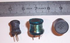
Let's have a word about the probes:
Here are three examples of 10mH chokes, like the one inside the general purpose magnetic sensor (the yellow one):
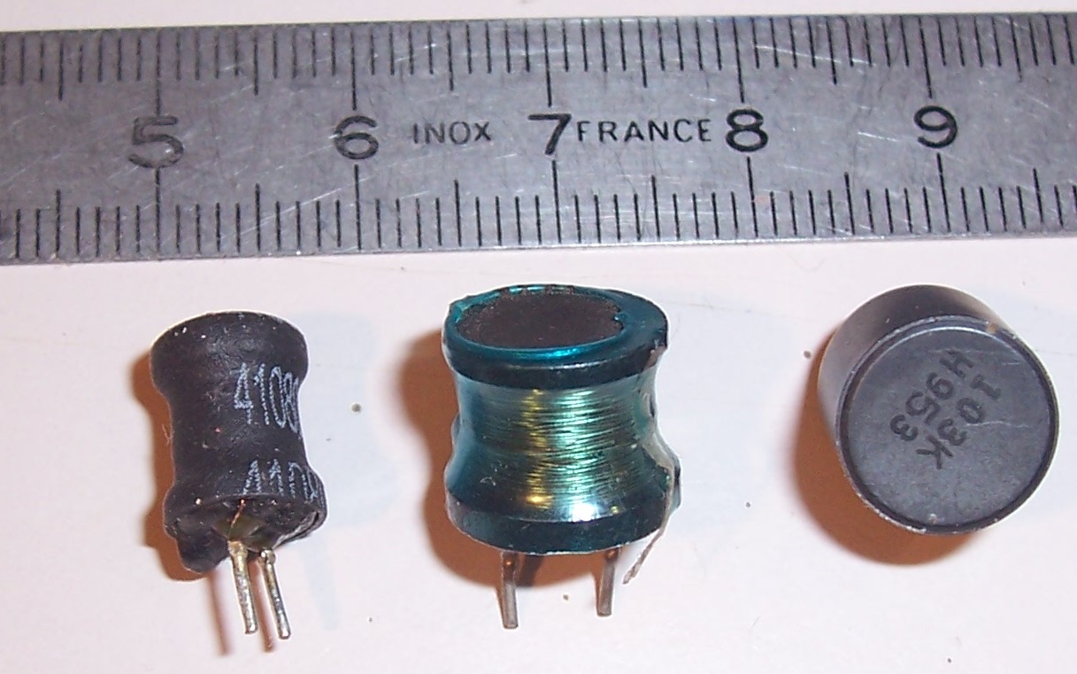
The one I used is the small black one on the left.
The next one is larger, and would provide a higher sensitivity: what matters is the cross-section.
That said, the small one is already sufficient to detect the magnetic field generated by a 100µA current at a distance of ~10mm.
Finally, the last one would be unsuitable: it has a ferrite cover and a low sensitivity to external fields.
The coil itself is the main component of the probe, but it is also recommended to include a parallel damping resistor, to kill possible resonances. I have used 1K, but it is not critical.
It is also necessary to cover the coil with an electrostatic shield, otherwise it will have a parasitic, unwanted sensitivity to E-fields too.
For E-fields, use the dedicated probe.
The shield is a copper foil covering the entirety of the coil, but the inner side has to be covered with an insulating foil, to avoid creating a shorted turn.
The shield is connected to the GND side of the coil.
All of this explains the awkward, irregular shape of the finished probe.
The pinpointing probe does not require a shield or a damping resistor: the impedance at 50/100/150Hz is too low to be affected by E-fields, and the steel core is conductive and has heavy magnetic losses sufficient to damp the inductance
Here are three examples of 10mH chokes, like the one inside the general purpose magnetic sensor (the yellow one):
The one I used is the small black one on the left.
The next one is larger, and would provide a higher sensitivity: what matters is the cross-section.
That said, the small one is already sufficient to detect the magnetic field generated by a 100µA current at a distance of ~10mm.
Finally, the last one would be unsuitable: it has a ferrite cover and a low sensitivity to external fields.
The coil itself is the main component of the probe, but it is also recommended to include a parallel damping resistor, to kill possible resonances. I have used 1K, but it is not critical.
It is also necessary to cover the coil with an electrostatic shield, otherwise it will have a parasitic, unwanted sensitivity to E-fields too.
For E-fields, use the dedicated probe.
The shield is a copper foil covering the entirety of the coil, but the inner side has to be covered with an insulating foil, to avoid creating a shorted turn.
The shield is connected to the GND side of the coil.
All of this explains the awkward, irregular shape of the finished probe.
The pinpointing probe does not require a shield or a damping resistor: the impedance at 50/100/150Hz is too low to be affected by E-fields, and the steel core is conductive and has heavy magnetic losses sufficient to damp the inductance
Attachments
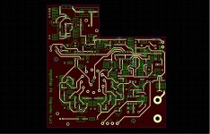
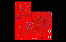
Here you are! I think it's ready. This is the version with all mods but I also have the original. BNC for in and out and banana chassis mount for DCSS to keep the pcb in place. All switches and connectors moved to bottom layer. I added a LED and a diode to protect from accidental reversed battery connection although not sure if it's necessary. I need to go to the local shop to look up on toggle and rotary switches to verify compatibility. Happy to upload both versions at anytime but they are not tested yet. This may take a while so patience please! Should you like to take your chances, just let me know...
Attachments
- Home
- Design & Build
- Equipment & Tools
- An effective weapon for your hum problems: the HumBoy