Do NOT touch any of the aligning elements! This is the domain of experts that meanwhile die away. And btw - in my youth I fumbled with many radios and repaired some - screwing each coil available. At the end the error never was misalignment - but some failing parts like capacitors or resistors, switching contacts etc.
A little late for that. The radio received one FM station when it was given to me many years ago. After refurb (tested and/or replaced all caps, resistors and the selenium diode, all new tubes and installed an inrush current limiter) it received about a dozen stations. If I brick it, it’s not a huge loss. But it’s in an awfully pretty mahogany case and I need some tunes in my shop. Plus, I’m looking at this as a learning experience, both of radios and my bench equipment, for which this exercise has already accomplished that objective.
Jeff
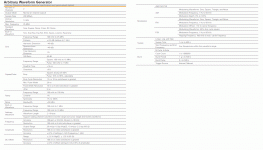
... FM capabilities? The modulation section is near the bottom.
That box has a lot of processing. More than _I_ ever had. My 2 cents says it would do FM at IF frequency.
Attachments
Those alignment instructions were written for the use of ancient analog instruments. The line frequency modulation drives the generator frequency sweep at the same time line frequency voltage is connected to the analog oscilloscope 'X' input in X-Y mode
To use a digital generator and scope, don't use X-Y. Use normal Y-T display mode. Compute the generator sweep ramp time, then set the digital scope horizontal to that time and use a generator trigger output signal as an external trigger input to the digital scope.
Each time the generator starts a sweep, the scope will trigger and also start its sweep. Since both have accurate digitally based timing, successive traces will be identically positioned so that you can see the effect of adjustments of the DUT.
Your goal is to adjust the scope settings so that the display shows one entire sweep ramp across the horizontal axis. When you have done that, the horizontal time per division multiplied by the number of divisions will be the sweep time.
Your scope vertical input needs to be connected to a voltage source that is proportional to signal level - either a test point in the receiver or an RF detector probe.
The generator portion of the scope is limited to 10 MHz. The IF is 10.7 MHz. You won't get there. And the modulation is done in a way that limits the max modulated frequency. This is typical of all the Arb gens. You would like as much as 500 KHz peak deviation +/- and you would like to know a specific deviation level to optimize the IF. Its bandwidth needs to be larger than the max transmitted deviation or you get serious distortion. And you need an effective band limit on the filtering to separate close stations. You then want to adjust the detector for maximum linearity.
The AFC will get its tuning correction from the detector. Until that's working right no AFC.
I think you need a real RF/IF generator to make progress.
However you could get a NanoVNA to align the IF with more precision than ever and possibly cheaper than an RF generator. However there will be a learning curve.
-xmo
Thanks. Now if I can figure out the components of that math I may be able to go that route.
-1audio
The SG actually goes up to 25Mhz. So I made some progress with the unmodulated steps requiring 10.7Mhz. But you are correct about the deviation limit.
What I’m wondering is, the scope has TWO identical generator channels and perhaps there is a way to combine the two to get the types of signal I need.
Again, I have been able to satisfactorily complete 3 of the 5 alignment steps that have resulted in improvement. Much to learn yet about the whole process. Thanks for your help.
Jeff
