In principle, DA by itself doesn't cause distortion: it is a purely linear effect
Yes this is what the model says, but... the real capacitor has the final word.
Just like "never trust the accuracy of an opamp that just came out of clipping"
Loss could be harmless resistance, but it could be hysteresis, and hysteresis is distortion...
I have searched the net for other sources of DA information, and the 0.6% value is the most commonly quoted for COG.
A few give even higher values, and one gave 0.1%, but for that one, the figures for other dielectrics looked unusual.
I suspect that the 0.6% has been copied/pasted many times, because people didn't care to actually measure the value (after all, for the typical applications of COG, mostly as a substitute for silver mica, DA doesn't really matter)
Makes sense. Not surprised by the results. C0G is almost as good as polypropylene in terms of distortion in filters that I have seen.
An interesting lesson to be learned from the test I performed at higher speeds is that the DA is mostly scale-invariant, at least for dielectrics and time-scales useful for audio and general signal processing.
This means that capacitance values smaller than 1nF, currently inaccessible to the DA-boy could be measurable with some adaptations.
The measurement floor of the DA-boy stems from a number of parasitic effects: sensitivity to stray AC fields and semi-variable electric fields caused by movements around the tester, leakage currents and charge-injection effects.
Sensitivity to electric fields can be fixed by a Faraday shield.
Increasing the cycle frequency can also help, and it fixes the leakage current issue: the charge the CUT can leak or gain can be reduced if the exposure duration to parasitic currents is reduced.
The charge-injection problem remains: when the discharge switch opens, it delivers a parasitic charge to the CUT, corrupting the low-level resolution.
With a faster cycle, the effect is aggravated if the maximum capacitance limit remains the same: the discharge has to be more energetic, requiring a bigger switch, having higher capacitances.
A better switch than the commodity-4066 would certainly be necessary, and charge-compensation techniques more elaborate than a simple adjustable capacitor would also help.
An evaluator made with slightly better components, a 30~40Hz cycle frequency and a bit more sophistication could probably reach 100pF.
With the current version of the DA-boy, all of the parasitic effects conspire to degrade the resolution very quickly under 1nF.
Last edited:
Yes, the charge injection only depends on the amplitude of the control signal, however the DA result with scaled up or down cycle times will not change if the relative durations remain in the same proportion.
The idea could be applied to the charge voltage though: if a dummy cycle using Vcharge=0 is performed, the value accumulated on the cap will be almost purely caused by charge injection, and could be used as an offset value (some "long term" memory voltage will also reappear, but it should be relatively small).
It would require a more elaborate sequencer than a pair of one-shots though, which is why I would prefer a purely static compensation first, like a dummy switch
I entered the schematic in Altium, can someone double-check?
Should offset trim be a screwdriver trimmer, multiturn, or pot?
Should the 1%/10% setting be a switch or 0.1" jumper?
If you want PCB switch for on/off and 1/10% gimme a part#
Should multimeter output be PCB banana plug?
If you want specific enclosure, need part# for location of screw holes. However, I won't spend extra time shrinking the PCB to minimum dimension.
Attachments
Last edited:
Thanks. Apart from the missing jumper spottted by Zung, and the mislabelled second half of the TLC272, everything looks fine.I entered the schematic in Altium, can someone double-check?
A single-turn trimmer is sufficient, and provides a visual indication of its setting.Should offset trim be a screwdriver trimmer, multiturn, or pot?
A switch, but 0.1" pad could be added in // for those wanting a minimalistic build.Should the 1%/10% setting be a switch or 0.1" jumper?
To avoid be tied to a too specific item, I'd say two separate parts (a single center-off switch could always be wired off-board), but if I can find an example having a foot-print common to many makers/types, I may propose one.If you want PCB switch for on/off and 1/10% gimme a part#
Yes with the standard 3/4" spacing, the GND on the left and hot on the right.Should multimeter output be PCB banana plug?
Again, normal pads in // costs nothing.
No, the circuit can be built in the "evaluation board/test-jig" style and used naked, with four holes in the corner to attach standoffs pillars serving as feet, or to screw it inside any custom box.If you want specific enclosure, need part# for location of screw holes.
Having the battery directly clipped on-board would be nice, for use as a standalone naked module.
Other members can express their preferences, as Zung did regarding the TH construction
I've done most of the routing.
> the circuit can be built in the "evaluation board/test-jig" style and used naked
Yes, I went with that.
> A single-turn trimmer is sufficient, and provides a visual indication of its setting.
OK
> A switch, but 0.1" pad could be added in // for those wanting a minimalistic build.
I'm putting a multi footprint PCB switch (push or toggle, cheapest of either on mouser), can be replace with header.
> Yes with the standard 3/4" spacing, the GND on the left and hot on the right.
OK
> Having the battery directly clipped on-board would be nice, for use as a standalone naked module.
Yeah, I also went with that, battery clips, "wireless" design.
OK, done.
I've put a trimmer and a pot for offset, if you put both you get coarse/fine.
No wire mess: battery clips, and 0.1" headers for the capacitor to test.
If the user wants an enclosure (I wont), all the knobs/LED/etc are on the same side, so that'll make a front panel. Except the output, but inside an enclosure, 2 wires should not make a mess.
Ground plane, with reference ground in the middle of the right side (GND pins of DUT, R11,C6, R14). Should I make a cutout? There should be no current flowing in ground anyway when the oscillator doesn't switch...
TODO:
I can't find the hole diameter for the 3/4" banana plugs, can you get me a part number?
I'll put holes for male plugs (to plug it into the multimeter) and female plugs (to plug banana test leads) so I'll need a part number for both.
Do you want a logo on the silkscreen? Like your Groland avatar?
Attachments


Another option is to combine both switches. This example is widespread among manufacturers, and exist as straight or 90° lever, slide, etc.
DPDT On Off On Switch - PCB Mount - Short Shaft - Love My Switches
The inter-row spacing is not specified, but it is 5.08mm.
Do as you please, or let the community decide
It is probably an unnecessary luxury, but people are free to implement it or notOK, done.
I've put a trimmer and a pot for offset, if you put both you get coarse/fine.
Currents are no big issue, cutout is not necessaryGround plane, with reference ground in the middle of the right side (GND pins of DUT, R11,C6, R14). Should I make a cutout? There should be no current flowing in ground anyway when the oscillator doesn't switch...
TODO:
I can't find the hole diameter for the 3/4" banana plugs, can you get me a part number?
They seem to exist in 3mm and 4mm.I'll put holes for male plugs (to plug it into the multimeter) and female plugs (to plug banana test leads) so I'll need a part number for both.
Here is an example (rather costly for such a small piece of hardware, but similar cheaper types should also exist):
https://benl.rs-online.com/web/p/ba...VGJzVCh31UwLvEAQYBCABEgI2jvD_BwE&gclsrc=aw.ds
I am not sure banana's are the best option for the test leads: for DUT <10nF, the capacitance of the input node wrt. ambience has to be kept at an absolute minimum, which is incompatible with any length of test lead.
The row of 0.1" terminals you have currently installed allows the option of plugging test leads for large values, and direct insertion for smaller values
Do you want a logo on the silkscreen? Like your Groland avatar?
Leave or remove it, you'll get your beer anyway
A good shielding is essential, but if the PCB capacitance is large, it risks creating an initial DA, because PCB materials are very poor in this respect.Is ground fill under all the traces and parts associated with CUT a disadvantage?
Here, the extent of the tracks seems reasonable and shouldn't be problematic
>I am not sure banana's are the best option for the test leads
I was thinking about connecting the multimeter with banana test leads, not the DUT. So that needs female banana sockets on the PCB. I found them, M6 thread.
So I'll put 4.5mm holes for M4 thread male bananas to stick in the multimeter directly, and 6.5mm holes for female banana sockets.
Hmmm, too lazy to change it lol
> The row of 0.1" terminals you have currently installed allows the option of plugging test leads for large values, and direct insertion for smaller values
Yes, that was the idea.
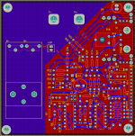
I've reduced capacitance: skinny traces, more copper pour clearance, and cutout to reduce capacitance between ground plane and resistors that will be right on top of it.
.PNG")
...but the cutout means slightly more e-field pickup.
I was thinking about connecting the multimeter with banana test leads, not the DUT. So that needs female banana sockets on the PCB. I found them, M6 thread.
So I'll put 4.5mm holes for M4 thread male bananas to stick in the multimeter directly, and 6.5mm holes for female banana sockets.
Another option is to combine both switches.
Hmmm, too lazy to change it lol
> The row of 0.1" terminals you have currently installed allows the option of plugging test leads for large values, and direct insertion for smaller values
Yes, that was the idea.
I've reduced capacitance: skinny traces, more copper pour clearance, and cutout to reduce capacitance between ground plane and resistors that will be right on top of it.
...but the cutout means slightly more e-field pickup.
Last edited:
OK, I see what you meanI was thinking about connecting the multimeter with banana test leads, not the DUT. So that needs female banana sockets on the PCB. I found them, M6 thread.
So I'll put 4.5mm holes for M4 thread male bananas to stick in the multimeter directly, and 6.5mm holes for female banana sockets
No problem!Hmmm, too lazy to change it lol
We have to chose between two evils. As I said, the capacitance doesn't look problematic, but for measuring low capacitances in a normal lab/workshop environment, the shielding is essential.I've reduced capacitance: skinny traces, more copper pour clearance, and cutout to reduce capacitance between ground plane and resistors that will be right on top of it
Therefore, I think it would be preferable to revert to the previous version, if you don't mind; or find some kind of tradeoff
- Home
- Design & Build
- Equipment & Tools
- A simple and easy Dielectric-Absorption evaluator, the D.A.-Boy