Hi there,
Here is another cheap & cheerful (and useful!) project: a dielectric absorption test-set.
What is DA (dielectric absorption)?
In a nutshell, DA is a parasitic effect affecting dielectric materials, and the capacitors they are made of.
Any real capacitor can be modelled as an infinite series of RC circuits.
In "good" capacitors, the first RC's total a large capacitance, and similar series resistances, resulting in an ideal cap in series with the ESR being the // sum of elementary R's.
Higher order effects are essentially minimal, and all of the losses are concentrated in the ESR, or the Q, the tan delta, the parallel damping resistance, .... etc: all these parameters are perfectly equivalent, and can be mathematically converted into any other one.
DA is somewhat different: although it counts as losses as it is a dissipative process, its real impact is absolutely minimal.
For example, mica is infamously known as one of the worst dielectric regarding DA, yet its losses remain very low.
This is the reason why this particular loss process has received a special treatment.
Although the energetic impact is minimal, the effect on the signals is far from negligible.
In dielectrics affected by DA, the elementary RC's of the series decrease more slowly, meaning a significant part of the total capacitance is hidden behind large R's, and large RC time-constants.
In practice, this means that when you attempt to charge or discharge such a cap very quickly, the farthest caps remain unaffected, and change the voltage and current after the event.
This delayed response leads to a host of unwanted effects, sometimes difficult to identify or attribute.
Some examples: the LF capacitance is larger than the HF one, sample-hold circuits show a small drop just after the sampling pulse, ramp generators have non-linearities, characterized by an excessive rise after the reset pulse, higher amplitude up to 50%, and lower amplitude afterwards.
It causes inaccuracies in the response of filters and equalization networks.
If you had the misguided idea of building a high-accuracy RIAA network from precision mica capacitors, the LF response would deviate from the ideal, even if you use 0.25% caps and 0.05% resistors.
In pulse circuits, it increases the settling time, in video signals, it causes streaking and lagging effects, and disrupts the black level, etc.
What causes DA?
The base dielectric material plays a major role, obviously, but many other factors also have an effect.
The presence of heterogeneities in the dielectric is an important one.
They can be discrete, like multi-sheet or multi-dielectrics caps, macroscopic as in layered materials like mica or granular materials like ceramics, or microscopic at the molecular level.
The presence of bubbles, voids, impurities, inclusions, wrinkles, fractures or other imperfections in the dielectric greatly increases the DA.
This means that composites, like PCB materials generally have a large DA.
The construction of the capacitor is extremely important: PP or PS are excellent dielectrics in theory, but a poor construction can totally ruin a capacitor based on these dielectrics.
Capacitors from the same production batch, in perfect condition, can display significant DA characteristics differences, even when all the rest is nominal.
DA is not systematically tested, but it is a good indicator of the quality and consistency of the production, as it is very sensitive to to the slightest contamination or deviation.
How is DA measured?
The universal method is to charge the CUT to a known voltage, keep it charged for a soaking time, discharge it briefly, let it recover completely disconnected, and finally measure the recovered voltage.
The ratio of the recovered voltage to the initial voltage is the DA value.
In this process, absolutely everything counts and influences the end result.
The only way to reproduce a result is to use strictly identical conditions.
Most accepted methods use time-scales of minutes or tens of minutes, and use mercury-wetted relays and similar devices.
Not very convenient for a fast, casual use.
The evaluator I propose does things more simply, but more importantly, it does so at a (comparatively) blindingly fast speed: the total cycle time is 1 second, and although the reading needs a little longer to settle, it is still tens of times faster than any "official" alternative.
What is the value of such an accelerated measurement?
Basically, it indicates DA when it is present and the parameters of the circuit have been tweaked to mimic "standard" results (remembering that there are in fact no such standards, it just follows the mainstream trend).
If you build the tester, you will have your own, stable reference, and if you test a number of known samples, you will get a feeling of what a good DA is.
If other DIYers build the same instrument, you will be able to compare your results with others.
The circuit is simple and cheap, based mostly on commodities except for the opamp, which is not especially rare or expensive and can easily be substituted.
I propose two versions: one is adjustment-free and has no bells and whistles like a low-batt. indicator, the other has compensations and adjustments to improve the absolute accuracy.
The evaluator will work from 1nF to 10µF without needing to switch anything, and has two ranges: 1% full range, and 10% full range.
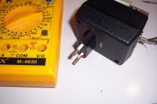
It is designed as a multimeter add-on, and plugs into the standard 3/4' spaced input ports of most digital multimeters: mains plugs and outlets use the same standard, meaning the tester is housed in the shell of an AC/DC wallwart.
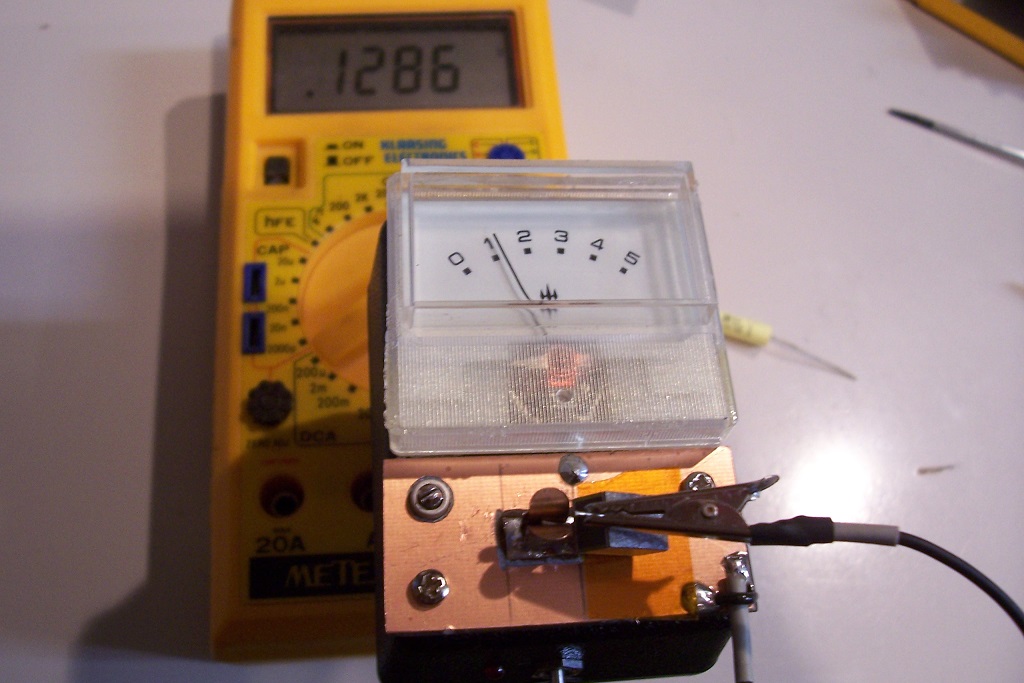
The "luxury" version includes a small galvanometer, allowing a stand-alone operation.
The sensitivity is sufficient to distinguish between two slightly different flavors of PP caps.
The 10% range is sufficient for reasonably good caps: PP, PS, PET, PC, ceramic COG or X7R.
It is insufficient for high-k ceramics, Ecaps, bad paper caps, but you don't need a tester to be aware of that.
If you really need to know the details, you can add a range having a lower gain.
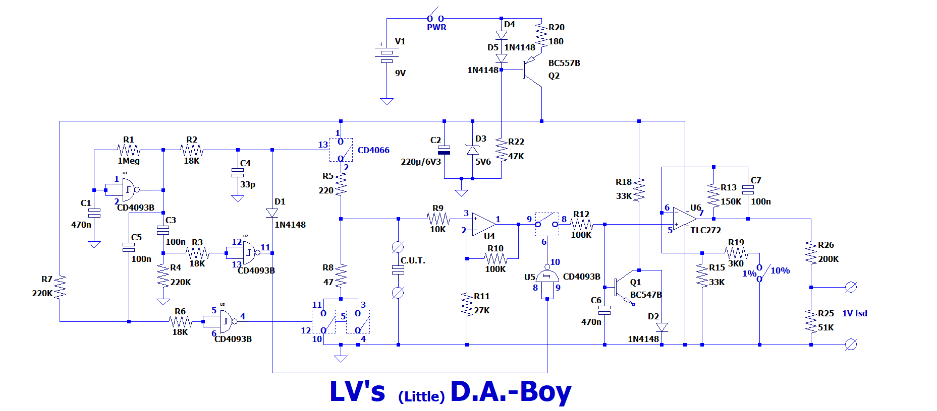
This is the "light" version:
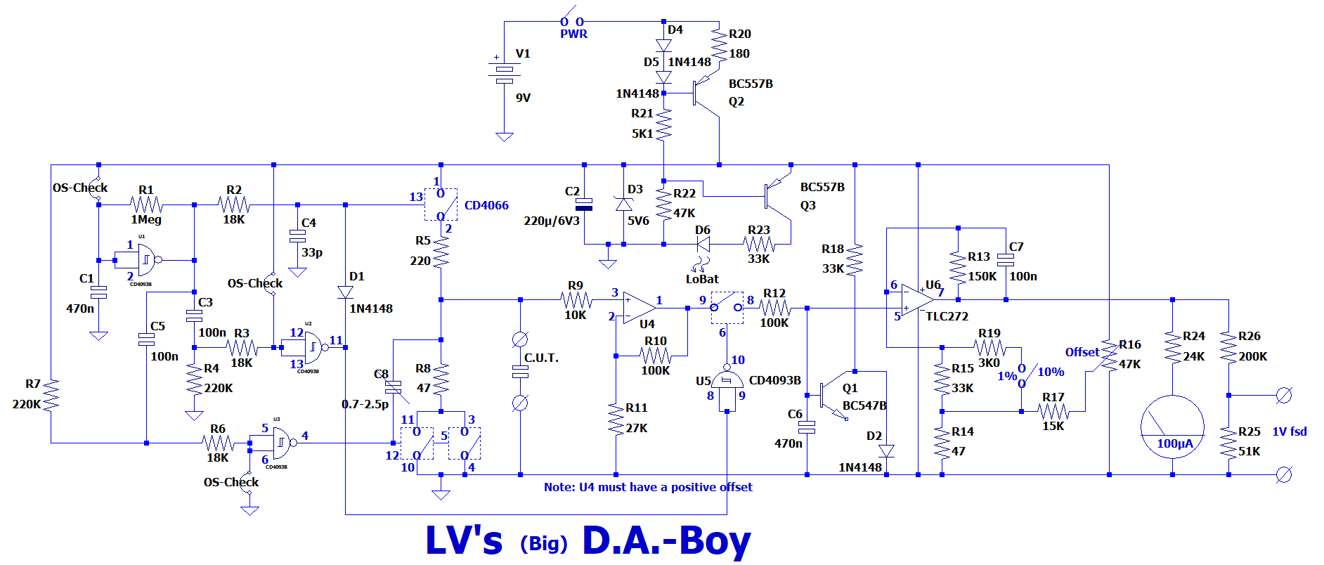
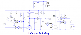
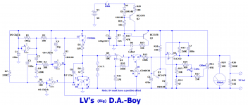
And this is the full one:
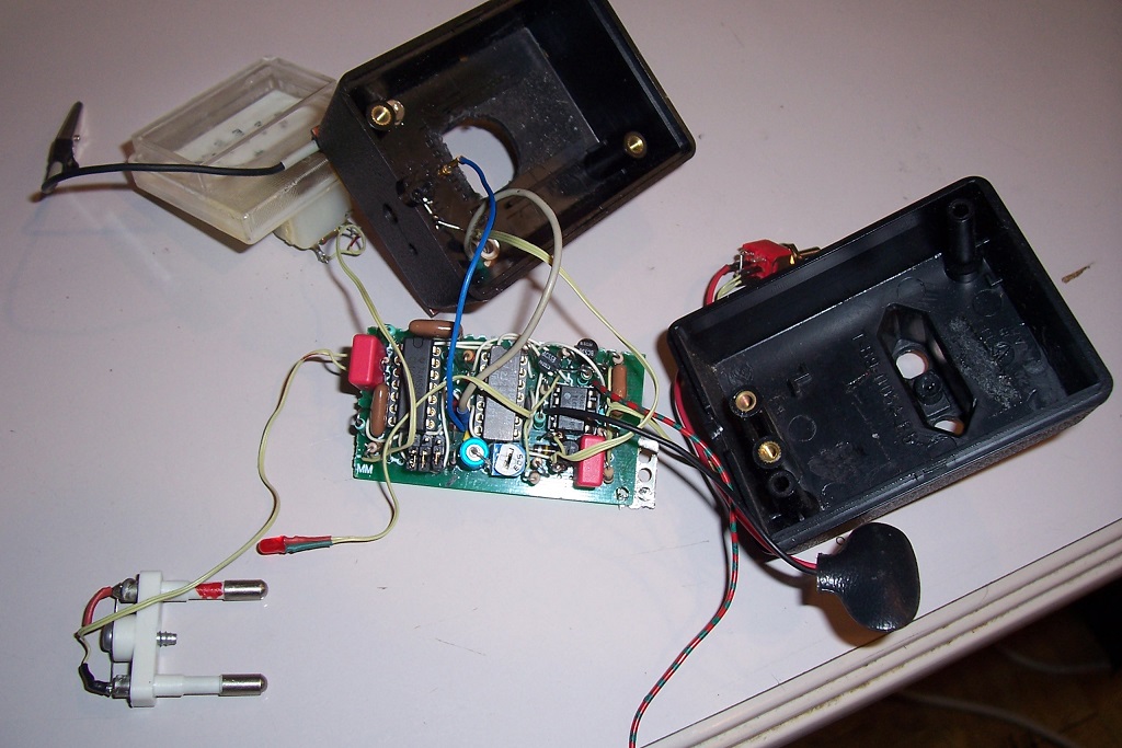
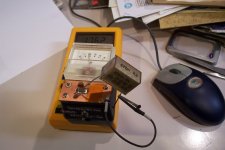
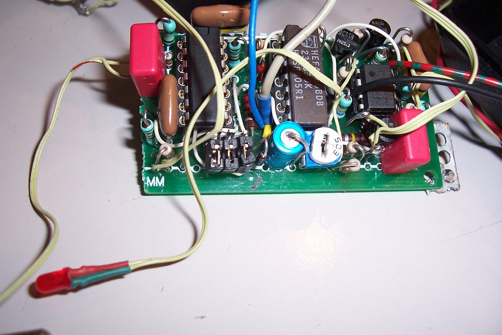
This is how my build looks:
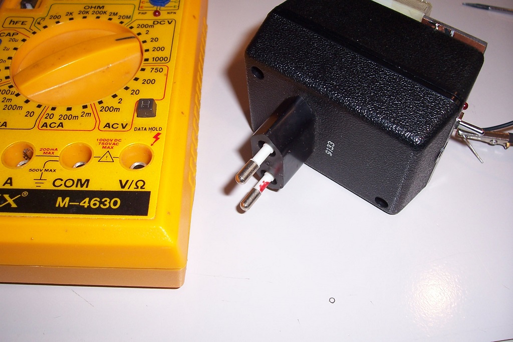

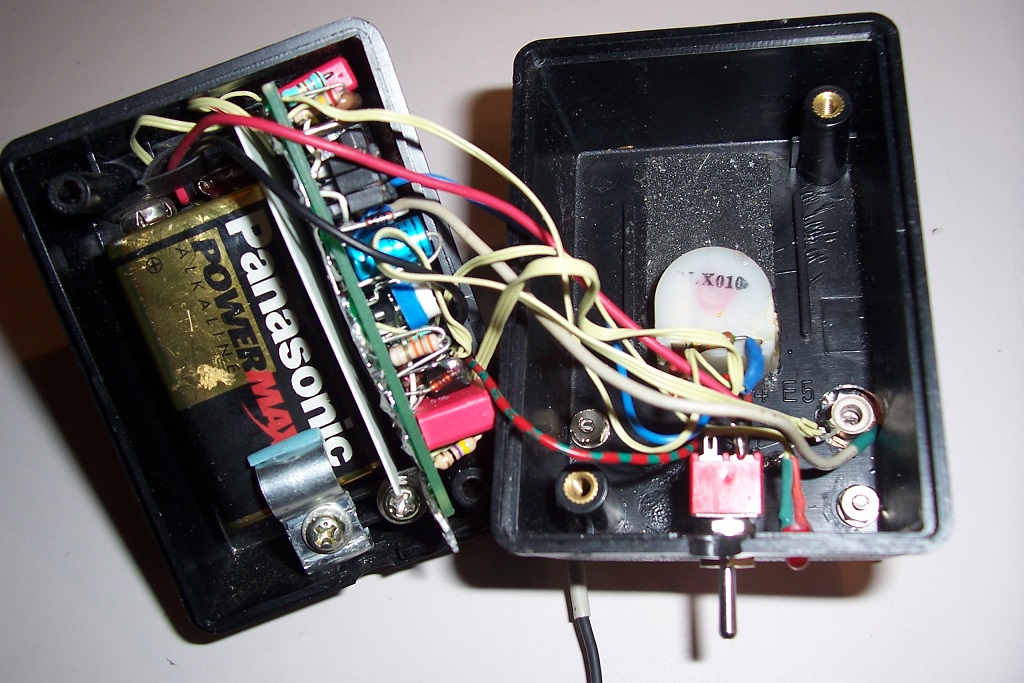
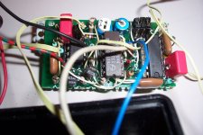
A look inside:
Here is another cheap & cheerful (and useful!) project: a dielectric absorption test-set.
What is DA (dielectric absorption)?
In a nutshell, DA is a parasitic effect affecting dielectric materials, and the capacitors they are made of.
Any real capacitor can be modelled as an infinite series of RC circuits.
In "good" capacitors, the first RC's total a large capacitance, and similar series resistances, resulting in an ideal cap in series with the ESR being the // sum of elementary R's.
Higher order effects are essentially minimal, and all of the losses are concentrated in the ESR, or the Q, the tan delta, the parallel damping resistance, .... etc: all these parameters are perfectly equivalent, and can be mathematically converted into any other one.
DA is somewhat different: although it counts as losses as it is a dissipative process, its real impact is absolutely minimal.
For example, mica is infamously known as one of the worst dielectric regarding DA, yet its losses remain very low.
This is the reason why this particular loss process has received a special treatment.
Although the energetic impact is minimal, the effect on the signals is far from negligible.
In dielectrics affected by DA, the elementary RC's of the series decrease more slowly, meaning a significant part of the total capacitance is hidden behind large R's, and large RC time-constants.
In practice, this means that when you attempt to charge or discharge such a cap very quickly, the farthest caps remain unaffected, and change the voltage and current after the event.
This delayed response leads to a host of unwanted effects, sometimes difficult to identify or attribute.
Some examples: the LF capacitance is larger than the HF one, sample-hold circuits show a small drop just after the sampling pulse, ramp generators have non-linearities, characterized by an excessive rise after the reset pulse, higher amplitude up to 50%, and lower amplitude afterwards.
It causes inaccuracies in the response of filters and equalization networks.
If you had the misguided idea of building a high-accuracy RIAA network from precision mica capacitors, the LF response would deviate from the ideal, even if you use 0.25% caps and 0.05% resistors.
In pulse circuits, it increases the settling time, in video signals, it causes streaking and lagging effects, and disrupts the black level, etc.
What causes DA?
The base dielectric material plays a major role, obviously, but many other factors also have an effect.
The presence of heterogeneities in the dielectric is an important one.
They can be discrete, like multi-sheet or multi-dielectrics caps, macroscopic as in layered materials like mica or granular materials like ceramics, or microscopic at the molecular level.
The presence of bubbles, voids, impurities, inclusions, wrinkles, fractures or other imperfections in the dielectric greatly increases the DA.
This means that composites, like PCB materials generally have a large DA.
The construction of the capacitor is extremely important: PP or PS are excellent dielectrics in theory, but a poor construction can totally ruin a capacitor based on these dielectrics.
Capacitors from the same production batch, in perfect condition, can display significant DA characteristics differences, even when all the rest is nominal.
DA is not systematically tested, but it is a good indicator of the quality and consistency of the production, as it is very sensitive to to the slightest contamination or deviation.
How is DA measured?
The universal method is to charge the CUT to a known voltage, keep it charged for a soaking time, discharge it briefly, let it recover completely disconnected, and finally measure the recovered voltage.
The ratio of the recovered voltage to the initial voltage is the DA value.
In this process, absolutely everything counts and influences the end result.
The only way to reproduce a result is to use strictly identical conditions.
Most accepted methods use time-scales of minutes or tens of minutes, and use mercury-wetted relays and similar devices.
Not very convenient for a fast, casual use.
The evaluator I propose does things more simply, but more importantly, it does so at a (comparatively) blindingly fast speed: the total cycle time is 1 second, and although the reading needs a little longer to settle, it is still tens of times faster than any "official" alternative.
What is the value of such an accelerated measurement?
Basically, it indicates DA when it is present and the parameters of the circuit have been tweaked to mimic "standard" results (remembering that there are in fact no such standards, it just follows the mainstream trend).
If you build the tester, you will have your own, stable reference, and if you test a number of known samples, you will get a feeling of what a good DA is.
If other DIYers build the same instrument, you will be able to compare your results with others.
The circuit is simple and cheap, based mostly on commodities except for the opamp, which is not especially rare or expensive and can easily be substituted.
I propose two versions: one is adjustment-free and has no bells and whistles like a low-batt. indicator, the other has compensations and adjustments to improve the absolute accuracy.
The evaluator will work from 1nF to 10µF without needing to switch anything, and has two ranges: 1% full range, and 10% full range.
It is designed as a multimeter add-on, and plugs into the standard 3/4' spaced input ports of most digital multimeters: mains plugs and outlets use the same standard, meaning the tester is housed in the shell of an AC/DC wallwart.
The "luxury" version includes a small galvanometer, allowing a stand-alone operation.
The sensitivity is sufficient to distinguish between two slightly different flavors of PP caps.
The 10% range is sufficient for reasonably good caps: PP, PS, PET, PC, ceramic COG or X7R.
It is insufficient for high-k ceramics, Ecaps, bad paper caps, but you don't need a tester to be aware of that.
If you really need to know the details, you can add a range having a lower gain.
This is the "light" version:
And this is the full one:
This is how my build looks:
A look inside:
Attachments


Q1 is used as cheap, low leakage clamping diode to prevent wind-up/long recovery times when the CUT terminals are open or short-circuited when the CUT is inserted.
Ordinary diodes like the 1N914 or 1N4148 are always doped, generally with gold to improve their Trr, but it severely increases the saturation and leakage currents which would seriously skew the results in this application.
Ordinary, plain vanilla types did exist, like the OA200 series or some 1Nxxx types, including a 1N6-something, but they are becoming very hard to get unless you are a big manufacturer.
A simple, cheap and easily available alternative is a junction of an ordinary small signal BJT.
When a really low leakage is required, the gate junction of a small jFet is the next best thing compared to real pA diodes.
Here, a simple BJT is sufficient.
All of the anti-windup circuitry can perfectly be omitted, the only downside will be a longer recovery time from overload
The different phases of the cycle are generated by a simple, one-shot-based sequencer.
The master 1Hz clock comes from a schmitt trigger oscillator, U1.
Its H level directly controls the charging switch, except the start is blanked by a one-shot, because it is in fact the final step when the voltage is sampled and measured.
When the H level period ends, another one-shot sends a pulse to the discharge switches.
The switches have series resistors limiting the charge/discharge currents, and protecting the IC in case a charged capacitor is inserted.
U4 amplifies the recovered voltage, which is sampled at the very end of the cycle by U5 and its S.H. switch.
Q1/D2 limit the voltage on the S.H. cap to ~1V, to reduce the recovery time.
U6 adds a gain of 5.5x or 55x before the indicator(s).
An offset control is also added at that stage, but because of the single supply, it can only cope with positive offsets.
I have included a small, inaccurate vumeter to provide a crude indication without needing to insert the tester into a multimeter.
The total gain is ~25, much more than the 10x required theoretically, to compensate for the accelerated cycle and obtain results comparable to other methods.
The supply is extremely simple, based on a shunt regulator and a CCS.
The total current consumption is just under 2mA, meaning an autonomy of many days.
The low battery indicator monitors the I-O difference and lights the low current LED when it is <0.4V.
The circuit operates down to a battery voltage of 6V.
The tester is designed to operate with capacitors from 1nF to 10µF.
The lower limit is set by parasitic charge injection from the switches, and also the high impedance during the recovery phase: a 1nF cap has a 3 megohm impedance at 50Hz, and the recovered voltage is in the mV range.
It can thus very easily catch the ambient hum.
The construction of the tester with a single spring "hot" terminal in the middlle of a ground plane, and the battery operation help a lot, but without additional shielding, it would be difficult to obtain a stable reading with low-DA caps in the hundreds of pF.
C8 compensates for the charge injection from the switches.
The 10µF upper limit is set by the discharge resistors and the length of the discharge pulse.
If required, the one-shot generating the discharge pulse could be set for a longer time, up to 2x the current value.
If the pulse is excessive, it will shorten the recovery phase.
Another possibility is to increase all the caps in the same proportion, it will lengthen the total cycle time.
Some other pics of the circuit:
Attachments

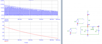
Certainly not: the recovered voltage that appears on the cap and is sampled and displayed cannot come from nowhere.What you are measuring is the dielectric absorption of the measuring equipment.
When you look at the CUT voltage evolution with an oscilloscope, you see that the shorting phase brings it to zero, but it rises again in the subsequent tens of ms, exactly like you see in the papers explaining DA and its measurement.
Anyway, a simple test shows that it measures something related to the DUT, not itself: if I test a PP or PS 10nF cap, I see a DA of 0.04 or 0.06%. With a 10nF polycarbonate, it rises to 0.1 ~ 0.2%. With a 10nF Mylar, it increases to 0.2 ~ 0.8%, depending on the manufacturing quality.
X7R ceramic is even higher, and Z-types ceramics are not measurable because they exceed the 10% of the max range
It is a simplified instrument, and some corners have been cut, but only to make the measurement quasi-instantaneous.D.A.-Boy seems to have a rather limited sophistication.
The values displayed might disagree (moderately) compared to "official" methods, but they are perfectly coherent internally and valid, and probably have more relevance for audio and signal electronics than methods operating in the minutes time scale.
Back to the subject:
To calibrate the Big Boy, you first need to find an opamp having a positive offset for the first operator (in principle, 1 in 2 should do).
Insert all the 3 test jumpers.
Turn the wiper of R16 fully towards the GND side. With the range switch in 1% position, measure the DC output of U6. If it is >1mV, it is OK. If it is smaller, try the next candidate.
Once you have found a suitable opamp, adjust R16 to arrive just at the GND level, say 0.2mV to be safe (there is no possibility to read a negative voltage, thus be careful not to "bury" the voltage below GND, as it is undetectable).
When it is done, remove the jumpers and insert a 1nF polystyrene or polypropylene cap of a known good quality, and adjust C8 to read 0.05%, or whatever value the cap is specified for.
Try a number of caps from different origins, to make sure you didn't use an atypical example.
Make this adjustment with a battery-operated multimeter, and far from any 50Hz source, using an isolated adjustment driver.
That's it.
The instrument is not a precision one, and anyway there is no definite standard you could use to calibrate it.
Once it is done, you will be able to measure all your caps according to the same reference -yours, and yours only-.
If other DIYers build the same, you will be able to compare your data with them.
There will also be a broad agreement with measurements made with another method, but some discrepancies will remain: even though gain corrections have been applied to dress up the results, the time-constants of dielectrics differ, and there is no way to reconcile all the values measured at different time-scales.
Update:
I have tested the measurement floor in better conditions, far away from any mains appliances or wiring.
With a "good" cap (polystyrene), the actual floor is ~200pF. With "bad" caps (ceramic or mica), the floor is obviously much lower, about ten times: around 22pF.
On ya Elvee.
Are the combination of parts particularly sensitive to long term changes in ambient temp, like say a 10C change between testing days ?
I guess simply placing the tester and a small battery operated DMM in a metal biscuit box (or aluminium BBQ drip tray that I often use for sensitive equipment) would be a simple way to alleviate ambient hum on the test bench.
No, not at all. The only sensitivity is to AC fields, when testing low value (thus high impedance) capacitors.On ya Elvee.
Are the combination of parts particularly sensitive to long term changes in ambient temp, like say a 10C change between testing days ?
Good idea: I shall test the measurement floor that way.I guess simply placing the tester and a small battery operated DMM in a metal biscuit box (or aluminium BBQ drip tray that I often use for sensitive equipment) would be a simple way to alleviate ambient hum on the test bench.
For normal use, it wouldn't be very practical.
When I was considering the building options, I thought of using a mobile Faraday cover, to be placed over the cap and the sensitive zone for difficult measurements, but I didn't implement it in the end.
Such measures are only required for C<5 to 10nF, and good quality.
For higher values and/or higher DA, no special precautions are required.
U4 and U6 are indeed MOS amplifiers: a TLC272.What are you using for U4? It would need to be an opamp with virtually no bias current (Mosfet?)
An additional requirement is that it has to include GND in its input and output range, but they are not rare: ST has a LinCMOS equivalent, and NS (now TI) had LMCxyz, also suitable.
AD too has certainly something suitable
I have made tests inside a biscuits tin, and slightly readjusted the charge compensation accordingly.
As a result, I need to revise the measurement floor again: for good caps (PS, PP, group I ceramics), it is back to 1nF: below, it is not possible to get reliable results.
Distinguishing "bad" caps, like mica or group II ceramics remains possible, but the details of good caps cannot be assessed.
To go lower, it would probably be necessary to better control charge-injection effects, by using something better than the cheapish 4066, or using a dummy switch to balance the charge rather than just an adjustable capacitor.
The construction would probably also need to be of a better standard, with a real PCB, guarding and a tight control on leakage currents.
A full metal case would also help.
What are the possible uses for this evaluator?
The immediately obvious application is the selection of parts for critical circuits, like precision filters, equalization circuits, ramp generators, AD and DA convertors.
It is not limited to that though: it can be used to identify the dielectric "signature" of an unknown capacitor, preferably in combination with other clues and information.
Conversely, it can provide very good information on the condition of a known capacitor: DA is very sensitive to the slightest degradation, resulting from manufacturing incidents, contamination, humidity ingress, etc.
You can have all the parameters like the nominal value, insulation resistance, tan delta completely normal, but if the DA deviates from the normal for this type of capacitor, you know that something unhealthy is in progress, and could lead to reliability problems in the future.
It can thus act as an early warning flag, capable of detecting problems well before they actually show in the target system
Last edited:
I was puzzled about your mentions of Mica being real bad for DA. I found the chart below at AVX https://www.avx.com/docs/techinfo/RFMicrowaveThinFilm/MLO_Dielectric_Absorption.pdf that suggests Mica is slightly better than NPO ceramic. I'm not sure what multilayer organic is but seeing the report makes it quite interesting. Teflon and Polystyrene are both also listed as quite good. The measurement method is also outlined.
This is a really good discussion of caps and mentions Mica DA as not being really good: Misc. Dielectrics
I'm sure good/bad is a judgement call relating to specific applications.
This is a really good discussion of caps and mentions Mica DA as not being really good: Misc. Dielectrics
I'm sure good/bad is a judgement call relating to specific applications.
Attachments
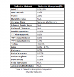
The values look broadly in line with those from other sources and my own measurements, except for one notable exception: NPO (COG) ceramic.
It is way too high, more like X7R ceramic.
The actual value for COG/NPO is only slightly worse than good plastics, it ranks among the best.
The quoted value for mica is generally worse than PET, which is a relatively bad plastic, and my measurements are in the same ballpark. I have found samples exceeding 1% though.
I have searched the net for other sources of DA information, and the 0.6% value is the most commonly quoted for COG.
A few give even higher values, and one gave 0.1%, but for that one, the figures for other dielectrics looked unusual.
I suspect that the 0.6% has been copied/pasted many times, because people didn't care to actually measure the value (after all, for the typical applications of COG, mostly as a substitute for silver mica, DA doesn't really matter)
I have tested a large number of samples, not only COG/NPO but other group I types.
For COG, I could only test MLCCs, because the value of disc or miniplate caps in this flavor is too low to be reliably tested with the DA-boy.
I can confirm that COG from Siemens are much better than 0.6%, lower than 0.1% in fact. Only the good plastic caps (PP and PS) do better than that.
For other, non-COG but group I, the value aren't always that good, and tend to degrade with higher values/higherTC.
The worst I tested was an old 820pF ERIE disc N2200 at 0.3%.
Other N1500 from CircleD were at 0.15%.
Lower tempco's were better and came close to the modern COG.
Run-of-the-mill mica caps tested between 0.4 and 1.2%.
Ultra high-end types made by BMC were at 0.2%, and excellent LCC's came close.
Of course, these figures are gathered with the DA-boy and its accelerated test procedure, and might not be comparable with values obtained with more conventional methods, but for films caps there is a very good agreement, and since film caps are used in integrators etc. their DA actually matters a lot, meaning the testing goes beyond copy/pasting historic values
It is certainly more relevant (or less irrelevant), but the time-scale of hundreds of ms would be ideal for the parts selection of slope-based A/D or D/A converters.
It would be instructive to make a "Flash DA-Boy" version, operating at 100Hz or higher, to see whether assumptions based on lower frequencies still hold.
That would be 100% relevant for audio applications.
I may try to breadboard such a tester
It would be instructive to make a "Flash DA-Boy" version, operating at 100Hz or higher, to see whether assumptions based on lower frequencies still hold.
That would be 100% relevant for audio applications.
I may try to breadboard such a tester
I may try to breadboard such a tester
OH YEAH
Here's an idea: open/close discharge switch at 1kHz. As the "hidden" caps keep re-charging the cap between each discharge, an AC voltage appears, that can be processed with soundcard, so no need for expensive test equipment.
Attachments
It is an interesting possibilty.
The translation factors from this method to results comparable with traditional methods would need some reflection.
A way to convert the DA value into a steady AC signal would probably ease matters.
In the meantime, I have breadboarded a flash version: I started modestly, with a 10x increase in frequency.
Everything seemed to work normally (I adapted the values that needed to, of course), and the behaviour of the caps appeared mostly unchanged: the DA effect seems to be practically scale-invariant regarding time, probably because of the quasi-fractal nature of the elementary capacitors series.
I then boldly pushed the frequency to 240Hz (again adapting the circuit, charge and discharge resistors, and using a MOSFET as discharge switch), and the behaviour remained almost identical: all the "good" caps, PS, PP, and importantly COG remained good, and all the "bad" caps, mica, PET, group II ceramics remained bad.
The only noticeable change was for polycarbonate (an intermediary dielectric, better than PET but not as good as PP): at higher speeds, the performance improved and came closer to PS/PP, without matching them though.
It might be that for very large time-scales, the COG performance degrades but I doubt it.
I cannot test this hypothesis with the DA-boy platform: too many parasitic effects like leakage currents would make such a down-scaling impractical for reasonable capacitor values.
This is very interesting Elvee, even for a rank amateur like me.
I’m not interested in the last word in accuracy, but certainly enjoy beholding circuits and testing the principles I have read about, in this case DA absorption, and go on to audition the sound to hear the difference for myself.
I have read that even among notionally good capacitors for audio, for example PP or Teflon, one occasionally appears that has higher distortion due to DA than other identical examples.
If this circuit is good enough to let me weed those out, I am building a Cordell distortion analyser and would like to hand select a few of the caps for lowest distortion, then it does what I need, would be fun to build and educational at the same time.
")
I’m not interested in the last word in accuracy, but certainly enjoy beholding circuits and testing the principles I have read about, in this case DA absorption, and go on to audition the sound to hear the difference for myself.
I have read that even among notionally good capacitors for audio, for example PP or Teflon, one occasionally appears that has higher distortion due to DA than other identical examples.
If this circuit is good enough to let me weed those out, I am building a Cordell distortion analyser and would like to hand select a few of the caps for lowest distortion, then it does what I need, would be fun to build and educational at the same time.
I then boldly pushed the frequency to 240Hz (again adapting the circuit, charge and discharge resistors, and using a MOSFET as discharge switch), and the behaviour remained almost identical: all the "good" caps, PS, PP, and importantly COG remained good, and all the "bad" caps, mica, PET, group II ceramics remained bad.
That's interesting!
In an audio context there is one cap where DA should really matter: the compensation cap used in amplifiers, because it sits on a very high impedance node so DA could potentially cause a delayed "offset" in the input stage after a transient, or lengthen the settling time...
Last edited:
As I remarked earlier, an increased DA is often the symptom of a more serious, underlying problem that has not matured yet.I have read that even among notionally good capacitors for audio, for example PP or Teflon, one occasionally appears that has higher distortion due to DA than other identical examples.
In principle, DA by itself doesn't cause distortion: it is a purely linear effect, and only distorts phase and frequency responses.
However, I have noticed that loss mechanisms make the bed of non-linearities, even if they do not cause them by themselves.
The least lossy capacitors and inductors generally have the best linearity.
A relatively lossy capacitor like PET will have a measurable but small distortion, and a low-loss type like PP will normally have an almost unmeasurable distortion, but if you find a PP cap having twice the characteristic losses of its dielectric, it will probably have a much higher non-linearity than the PET one, even though its absolute losses might still be 10x lower.
Among all the loss mechanisms, DA seems to be the most sensitive to problems.
DA is normally not systematically production-tested, because it requires some time and precautions, but it is periodically checked, and when a lot shows issues, it is totally discarded.
General losses like tan delta or Q, etc remain a good and accessible way of evaluating capacitors, but DA is probably the most sensitive and is quite accessible, as the DA-boy shows.
Even if you build the uncalibrated, simplified version you will still be able to rank capacitors; the absolute value for small and/or low-DA types will be meaningless, but you will still be able to determine which one is the best.
Indeed, and the traditional advice was to use something like silver mica, which is extremely poor, but in some case it can be part of the solution, because the complex impedance can help massaging the squarewave response.That's interesting!
In an audio context there is one cap where DA should really matter: the compensation cap used in amplifiers, because it sits on a very high impedance node so DA could potentially cause a delayed "offset" in the input stage after a transient, or lengthen the settling time...
Even when no high impedance is involved, the DA can cause inaccuracies: I took an extreme example of a RIAA correction network, but there are probably other places where DA can degrade the ultimate accuracy.
In analog video, where the frequency range was very large it caused various problems like streaking (trainage)
- Home
- Design & Build
- Equipment & Tools
- A simple and easy Dielectric-Absorption evaluator, the D.A.-Boy