Tradeoff: I'll keep the skinny traces for lower capacitance, but put the ground plane back. It felt wrong removing it anyway.

I've remembered wires love to pick up noise, so I've also added footprints for output filter cap. In case this ends up inside a "shielded" cookie box, also a 50R resistor, and removed a bit of soldermask on the ground plane, to solder a coax.

I've remembered wires love to pick up noise, so I've also added footprints for output filter cap. In case this ends up inside a "shielded" cookie box, also a 50R resistor, and removed a bit of soldermask on the ground plane, to solder a coax.
OK, next step: order the parts and check they fit in the holes (especially the switches, pot, 9V battery tabs, and bananas).
However, I'm a cheap bastard so I like free shipping, and DABoy is too cheap! So, that'll have to wait until my mouser shopping backet goes over 60€ lol. Unless someone else volunteers, of course!
However, I'm a cheap bastard so I like free shipping, and DABoy is too cheap! So, that'll have to wait until my mouser shopping backet goes over 60€ lol. Unless someone else volunteers, of course!
I have slightly revised the gain structure to avoid saturation near the max reading:
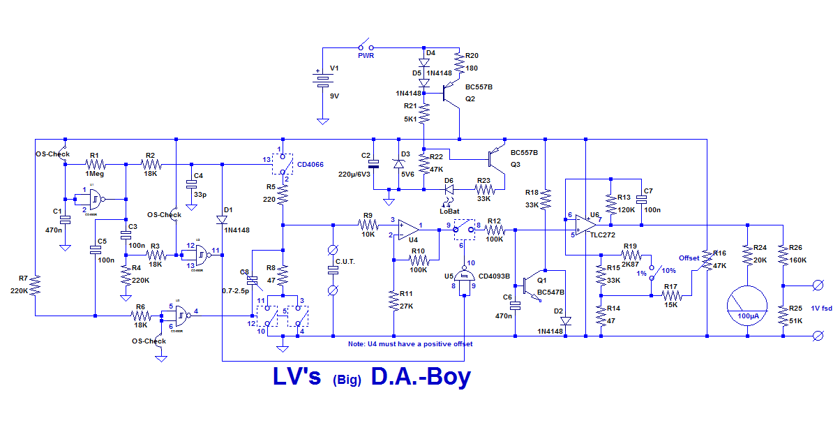
I have adapted the BOM.
The adjustable capacitor is going to pose unexpected problems: it has become extremely difficult to find low-cost models.
Provisionally, I have placed an example in the BOM, but it costs 4.7€, yet it is the least expensive I could find. It would be impossible to order anyway, as the minimum qty is 1.5k.
It will probably be necessary to use the old HAM trick of a small bit of coaxial pruned until it has the right capacitance.
Series connection might reduce the charge injection, but that is far from certain; the opposite could be true
I have adapted the BOM.
The adjustable capacitor is going to pose unexpected problems: it has become extremely difficult to find low-cost models.
Provisionally, I have placed an example in the BOM, but it costs 4.7€, yet it is the least expensive I could find. It would be impossible to order anyway, as the minimum qty is 1.5k.
It will probably be necessary to use the old HAM trick of a small bit of coaxial pruned until it has the right capacitance.
They are paralleled to reduce their resistance. A higher resistance would mean a lower maximum measurable capacitance value (The CUT needs to be totally discharged before being left open).Elvee, would there be any benefit from putting the two 4066 switches in series rather than parallel ?
Series connection might reduce the charge injection, but that is far from certain; the opposite could be true
Attachments

Just found adjustable caps on Aliexpress (free shipping) and Reichelt...
I'll probably use 2 wires twisted together or a bit of coax.
I'll probably use 2 wires twisted together or a bit of coax.
The ones from Chinese origin are probably better suited, as they go down to 3pF max value.
The one from Reichelt has a minimum value of 1.5pF, which might be excessive (it will depend on the PCB).
In addition, they are 1/10th of the price, and shipping is free.
Found them on banggood too: 10pcs 6mm trimmer variable ceramic capacitor 3pf 5pf 10pf 20pf 30pf 40pf 50pf 60pf 70pf 120pf adjustable capacitors Sale - Banggood.com
- Home
- Design & Build
- Equipment & Tools
- A simple and easy Dielectric-Absorption evaluator, the D.A.-Boy