Rohde & Schwarz UPD: #2 Troubleshoot then Restore to Glory
The A at the top here goes after the A of the #1
thread with the same name. Think of it like coding algorithms of old where
you have the circle around a letter or number and that means to go to that
page.
If I need to remove this bold text first please advise.
Everyman, this new thread is for troubleshooting the UPD. I have one that used
to work but one day just wouldn't start up any more. I asked some questions over
in the Rohde & Schwarz UPD - Help I've fallen and I won't start up thread.
I'm posting here, because I really think it best to start a new thread.
Maybe some of you other DIYers will join in and share your knowledge and experiences, please.
Now we can have a fresh approach to trouble shooting and working as a team,
sharing DIYAudio's collective skills, knowledge, and experience
troubleshooting, maintaining, and upgrading UPDs when possible.
Cheers,
A
Link
This thread
gets appended to the end
of the one with
the same name.
Please remove this
bold text when accomplished.
Thank you.
Link
This thread
gets appended to the end
of the one with
the same name.
Please remove this
bold text when accomplished.
Thank you.
The A at the top here goes after the A of the #1
thread with the same name. Think of it like coding algorithms of old where
you have the circle around a letter or number and that means to go to that
page.
If I need to remove this bold text first please advise.
Everyman, this new thread is for troubleshooting the UPD. I have one that used
to work but one day just wouldn't start up any more. I asked some questions over
in the Rohde & Schwarz UPD - Help I've fallen and I won't start up thread.
I'm posting here, because I really think it best to start a new thread.
Maybe some of you other DIYers will join in and share your knowledge and experiences, please.
Now we can have a fresh approach to trouble shooting and working as a team,
sharing DIYAudio's collective skills, knowledge, and experience
troubleshooting, maintaining, and upgrading UPDs when possible.
Cheers,
Last edited:
If your UPD is anything like the UPV, you will be able to test the PSUs in isolation. That's your first port of call.
Next, I would locate all power rail test points on each PCB, and measure their resistance to their relevant ground (if anything like a UPV, it will have multiple isolated grounds - so be sure to reference the right one). We have a UPV that has a short to 0V on an analogue rail, and I think we will either have to get a thermal camera, or maybe try freezer spray (after using a marker pen to highlight all parts that connect to 0V that could short).
If a PSU rail is out, then it's likely to have a root cause somewhere, so that'll need tracking down. From what I can see, these things can go wrong like a stack of dominoes - and it'll be rare to have just one fault (although one hopes it is!).
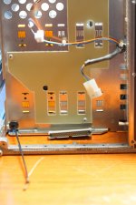
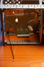
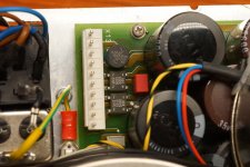
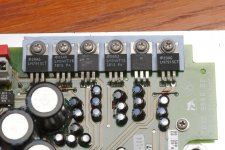
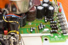
upd linear power supply
Some pictures of Power supply
Some pictures of Power supply
Attachments
-
 DSC06159-min.jpg348.9 KB · Views: 330
 -
 DSC06161-min.jpg326.8 KB · Views: 340
 -
 DSC06163-min.jpg765.6 KB · Views: 327
 -
 DSC06164-min.jpg760 KB · Views: 321
 -
 DSC06165-min.jpg977.6 KB · Views: 329
 -
 DSC06166-min.jpg892.4 KB · Views: 138
 -
 DSC06168-min.jpg955.3 KB · Views: 144
 -
 DSC06169-min.jpg878.8 KB · Views: 162
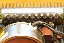
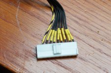
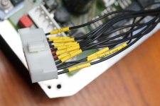
upd-transformator
measurments on x13 connector and input voltage 238.5V
measurments are between black -yellow 1-8 pins
1:33V
2:12.75V
3:7.67V
4:38.1V
5:7.22V
6:23.68V
7:16.43V
8:6.7V
measurments on x12 connector
measured between 1 and rest of pins.
2:26.39V
3:52.64V
4:19.7V
5:30.65V
6:1.3V
7:21.77V
8:42.45V
9:15.92V
10:24.65V
I didn look any schematics just quick measurments.
Attachments
Demian,
The boards are Rohde & Schwarz boards. The only other board that I saw in mine
was the GPIB board which was made in china. Now because the boards are
Rohde & Schwarz boards, does that mean they didn't farm then out and have
a standard manufacturer put R&S name on the motherboard?
I know that my moterboard is ver 1.2. Jeanlucdemarc's board is ver 2.0.
For me, I need to think how to proceed.
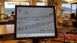
Since we are talking about motherboards.. While I as tryn to clone my hdd.. I put hdd to some other pc and accidentally started the upd program and result you can see on attached picture. So I assume that we could have any mother board inside as long we can connect it.
As or clone te hdd.. I tryed about 6 programs none could actually detect hdd until I tryed Clonezilla which works like "self containing dos" I don't know how to describe.. But YOUTUBE helped.
Next step : install dos 7.1 and upd on SD card thrue virtual machine (I need to trick virtual machine that installs directly on SD card).
Attachments
Jean, I agree to use a virtual machine, which may be the best choice for our purpose! I tried some other software to format a CF card and virtual HDD, but such disks usually didn't boot DOS. I think their CHS parameters are not compatible with DOS, but I couldn't fix them.
IIRC VMware support physical disk, including SD card on USB. But I used virtual HDD on virtualbox and cloned to a CF card. It clones the partition table as-is.
IIRC VMware support physical disk, including SD card on USB. But I used virtual HDD on virtualbox and cloned to a CF card. It clones the partition table as-is.
Gentlemen: thermionic, jeanlucdemarc, electronic, Shinja,
Since I have the UPD apart, with jeanlucdemarc's listed the voltages present
on his connectors, I assume that should be an issue as it's raw unloaded
power supply.
I'll post them after I measure them tonight, assuming we still have power here
in Texas. The whole state is in crisis from the worst winter storm in more that
100 years.
Cheers,
PS - Moderator anatec is in the process of moving about 1/3 of the UPD HELP posts
over to this thread. They should show up any time now.
jeanlucdemarc's measurements on left side, on x13 connector and input voltage 238.5V;
SyncTronX measurements right side, with input voltage of 120.0V.
measurements in VAC.
measurements are between black -yellow 1-8 pins
1: 33V 10.68V
2: 12.75V 1.74V
3: 7.67V 7.20V
4: 38.1V 18.56V
5: 7.22V 1.69V
6: 23.68V 15.0V
7: 16.43V 3.0V
8: 6.7V 0.412V
measurements on x12 connector
measured between 1 and rest of pins.
2: 26.39V 27.10V
3: 52.64V 54.38V
4: 19.7V 11.87V
5: 30.65V 18.39V
6: 1.3V 0.499V
7: 21.77V 5.37V
8: 42.45V 10.28V
9: 15.92V 3.81V
10 :24.65V 5.79V
jeanlucdemarc: "I didn't look any schematics just quick measurements."
Obviously this former working unit has power supply issues.
Are these related to parts baking when the unit didn't "turn on" no fan and no screen?
Are these related to capacitor failure mode of almost every cap in the main power supply?
Are these failures of the correlating power ICs?
Or a combination of the above?
As thermionic stated, "If your UPD is anything like the UPV,
you will be able to test the PSUs in isolation. That's your first port of call."
Well we made it to the port and found raiders and pirates trying to take
our vessel. We quickly came hard a starboard and raised what sail we could
from the bowsprit's flying jib through the foresail up to fore skysail,
through the mainsail up to the staysail and finally the spanker on the mizzen up to the mizzen skysail.
Aayyee, there lot's more work to do and we lived to sail another day.
Cheers Maties grog for the lot of you,
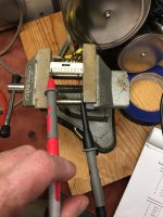
Spent about an hour trying to get the gunk out of the mother board.
On the left is the "measuring jig," on the right my little girl making Freckles into Peter Pan.
SyncTronX measurements right side, with input voltage of 120.0V.
measurements in VAC.
measurements are between black -yellow 1-8 pins
1: 33V 10.68V
2: 12.75V 1.74V
3: 7.67V 7.20V
4: 38.1V 18.56V
5: 7.22V 1.69V
6: 23.68V 15.0V
7: 16.43V 3.0V
8: 6.7V 0.412V
measurements on x12 connector
measured between 1 and rest of pins.
2: 26.39V 27.10V
3: 52.64V 54.38V
4: 19.7V 11.87V
5: 30.65V 18.39V
6: 1.3V 0.499V
7: 21.77V 5.37V
8: 42.45V 10.28V
9: 15.92V 3.81V
10 :24.65V 5.79V
jeanlucdemarc: "I didn't look any schematics just quick measurements."
Obviously this former working unit has power supply issues.
Are these related to parts baking when the unit didn't "turn on" no fan and no screen?
Are these related to capacitor failure mode of almost every cap in the main power supply?
Are these failures of the correlating power ICs?
Or a combination of the above?
As thermionic stated, "If your UPD is anything like the UPV,
you will be able to test the PSUs in isolation. That's your first port of call."
Well we made it to the port and found raiders and pirates trying to take
our vessel. We quickly came hard a starboard and raised what sail we could
from the bowsprit's flying jib through the foresail up to fore skysail,
through the mainsail up to the staysail and finally the spanker on the mizzen up to the mizzen skysail.
Aayyee, there lot's more work to do and we lived to sail another day.
Cheers Maties grog for the lot of you,
Spent about an hour trying to get the gunk out of the mother board.
On the left is the "measuring jig," on the right my little girl making Freckles into Peter Pan.
Attachments

Last edited:
So order of checking the for each power supply IC:
1. Check the power regulator IC
2. Check its diode.
3a. Check the smaller caps, ESR in circuit
3b. Pull them out of circuit and test again
4. if there are failures, then I replace all the
small caps on the power supply board.
QUESTION: Standard electrolytics or the solid polytype lytics?
Will the regulators tolerate the lower esr of those?
5. Leads me to contemplate the larger capacitors on the power supply.
Test them, or just spend 10s or 20s of dollars to buy new even if they are good?
To save time, instead of buying one lot of caps, then another, then another and
so on.
Then I have the individual boards to test and consider.
This is going to be challenging. And I'll keep in mind
what thermionic said
dominoes downstream failed also.
I've had enough joy for the evening.
Oh maybe Freckles the Peter Pan dog is being tortured too?
Cheers,
1. Check the power regulator IC
2. Check its diode.
3a. Check the smaller caps, ESR in circuit
3b. Pull them out of circuit and test again
4. if there are failures, then I replace all the
small caps on the power supply board.
QUESTION: Standard electrolytics or the solid polytype lytics?
Will the regulators tolerate the lower esr of those?
5. Leads me to contemplate the larger capacitors on the power supply.
Test them, or just spend 10s or 20s of dollars to buy new even if they are good?
To save time, instead of buying one lot of caps, then another, then another and
so on.
Then I have the individual boards to test and consider.
This is going to be challenging. And I'll keep in mind
what thermionic said
It's like the whole PSU is out, now I wonder what(snippage)
If a PSU rail is out, then it's likely to have a root cause somewhere, so that'll need tracking down. From what I can see, these things can go wrong like a stack of dominoes - and it'll be rare to have just one fault (although one hopes it is!).
dominoes downstream failed also.
I've had enough joy for the evening.
Oh maybe Freckles the Peter Pan dog is being tortured too?
Cheers,
Last edited:
I would stick 100% to the type of cap, as well as value that R+S have chosen. Larger electrolytics will have higher in-rush current, which could blow rectifiers. They could also have other effects, if it means that the PSU takes longer to stabilise on turn-on.
The voltage on the trafo secondaries may be a little higher when they aren't loaded, but the voltage at the VReg outputs should be correct, so you ought to be able to test a psu in isolation.
If you are worried about a component shorting from 0V to a power rail, then you need to locate the power test points on each PCB, disconnect any cables to / from other boards, and measure resistance. You want to see a very high reading that's symmetrical between rails.
My (basic) level of trouble-shooting extends to the UPV and no other R+S models, so the help I can give is pretty basic. I hope this helps!
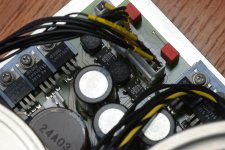
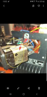
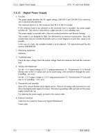
I had EMI failed (se attached picture) and replaced with FN378-4/21 that is all that i had to do with my Linear power supply. Seller said that my power supply is new and I belive that.
One thing i change : I switched from 230 to 240V because we have all ways more on 240V.. And i tasted that with varijak so.. the voltages should be correct on uloaded transformator.
SyncTronx my be someone overloaded your transformer or check what voltage you have selected on Eu plug connector.
Dont change kondenzators R&S made very good power supply (only on highest end you will see enclosed transformator). But if you want to improve Output U on linear rails should be addicional filters ..but dont")
I could say there is no need.
One thing i change : I switched from 230 to 240V because we have all ways more on 240V.. And i tasted that with varijak so.. the voltages should be correct on uloaded transformator.
SyncTronx my be someone overloaded your transformer or check what voltage you have selected on Eu plug connector.
Dont change kondenzators R&S made very good power supply (only on highest end you will see enclosed transformator). But if you want to improve Output U on linear rails should be addicional filters ..but dont
I could say there is no need.
Attachments
UPD's analyzer frontend is isolated from the chassis ground, so I think they may have isolated PSU. It is better to check it before DC voltage measurement, they may not share common ground.
Anyway, It is better to repair one by one, PC motherboard first and investigate another after that.
Anyway, It is better to repair one by one, PC motherboard first and investigate another after that.
Last edited:
thanks: thermionic, jeanlucdemarc, Sinja:
thermionic -- yes, I had the same thoughts about this, keeping the cap values the same,
and the type of capacitor if needed. The whole PSU is removed from the UPD and
tested the same manner as jeanlucemarc did. Most of my voltage reading were
about 1/3 of his. Puzzling, as this is a USA unit that that had undergone calibration
at some point and didn't need further calibrations. Basic guidance for now is what
I need and it helps me focus on what I need to do and not think in overly complex
terms. Knowing that I should have very high resistances between rails is a good think. Thanks, and yes it's helpful.
jeanlucedmarc -- Both our power supplies are removed from the UPD.
I will double check the EMI filter and verify the voltage setting should be
set to 120 VAC as this was and is a US used analyzer.
Also, very good points again regarding capacitors.
Sinja -- Yes, and my PSU is isolated. And yes, that is why I'm checking the PSU
before doing anything else. As you mentiond also, checking and repairing
one by one, by verifying in order:
1. PSU
2. SMPS
3. Mutha' board
4. Individual boards
Cheers,
Reflecting on the measurements I made:
The x13 connector:
Pin3 along is in spec
The x12 connector:
Pin 2 in spec
Pin 3 in spec
I don't think the Vregs can make up the differences can they?
I haven't looked at the data sheets, and I haven't mapped
the xnn connector pin to the applicable Vreg.
I should be able to measure resistanc from connect pin
to the input of each Vreg.
I'm also looking for James Perozzo's texts: "Systematic Electronic Troubleshooting"
and "The Complete Guide to Electronics Troubleshooting" as I have both and use
them. Confessing here, that I'm not much of a librarian, they are on a shelf somewhere,
but where? My bench and books are somewhat like Jim Williams or Bob Pease's though
I'm not in their league.
Cheers.
- Home
- Design & Build
- Equipment & Tools
- Rohde & Schwarz UPD: Troubleshoot then Restore to Glory