Demian, Steve, I get what you are saying.
I kept everything connected for now and took
and other set of measurements.
Oh, I didn't know that some were dual positive and
negative. Hmmm that changes my thinking a little
bit. Time to check data sheets again.
This time, not just with the open transformer cable, but
with them connected to the power supply. Then I measured
the pins on the board and have different measurements than
the first time around.
Time needed to let your comments simmer in the brain.
It doesn't always make sense to me the first time I read
or hear it, so I'll let things simmer in for a while and
get back to it.
I forgot to upload them.
Cheers,
Attachments

Last edited:
You said in Post 41:
May I suggest we assume for the moment that it’s correct until experiment disproves. Would you take just four measurements, with AC power applied, and see where the results lead us:
1. AC voltage across the two ~ terminals of the round bridge rectifier package. (This should be the transformer voltage but measuring at the package pins includes several potentially open circuit traces, connector opens, etc.)
2. DC voltage across C4, measured at the C4’s terminals.
And similarly:
3. AC voltage across the two ~ terminals of the square bridge rectifier package.
4. DC voltage across C6, measured at the C6’s terminals.
Thanks and good luck!
Steve
But you also said in Post 33:Oh, I didn't know that some were dual positive and
negative. Hmmm that changes my thinking a little
bit. Time to check data sheets again.
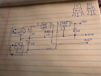
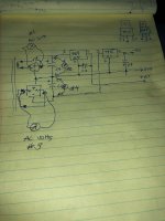
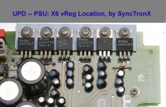
It was your Post 33 that led me to sketch a tentative schematic for a +15V/-15V regulator pair, included again for convenience.What is strange is that I can trace some of the vReg input pins
and output pins through their capacitors to the bridge rectifier.
And, it has continuity to both the bridge pos and bridge neg terminals.
May I suggest we assume for the moment that it’s correct until experiment disproves. Would you take just four measurements, with AC power applied, and see where the results lead us:
1. AC voltage across the two ~ terminals of the round bridge rectifier package. (This should be the transformer voltage but measuring at the package pins includes several potentially open circuit traces, connector opens, etc.)
2. DC voltage across C4, measured at the C4’s terminals.
And similarly:
3. AC voltage across the two ~ terminals of the square bridge rectifier package.
4. DC voltage across C6, measured at the C6’s terminals.
Thanks and good luck!
Steve
Attachments
Last edited:
1. 11.8 VAC round bridge rectifier.May I suggest we assume for the moment that it’s correct until experiment disproves. Would you take just four measurements, with AC power applied, and see where the results lead us:
1. AC voltage across the two ~ terminals of the round bridge rectifier package. (This should be the transformer voltage but measuring at the package pins includes several potentially open circuit traces, connector opens, etc.)
2. DC voltage across C4, measured at the C4’s terminals.
3. AC voltage across the two ~ terminals of the square bridge rectifier package.
4. DC voltage across C6, measured at the C6’s terminals.
2. 35.4 Vdc cap C4.
3. 53.8 VAC square bridge rectifier
4. 35.5 Vdc cap C6.
From these measurements the round bridge isn't supplying C4
or it may also be feeding it but it isn't the main supply for it.
AND
As long as I'm in here I might as well measure the other set of
bridge rectifier and caps 2, 1 to see if there are any differences.
That would tell me if these two circuits are different at their
smoothing capacitors.
Measuring for vRegs 2 and 1 and their related capacitors and their bridge rectifiers, they measure the same:
5. 11.8 VAC far round bridge rectifier.
6. 35.4 Vdc cap C2.
7. 53.9 VAC far square bridge rectifier.
8. 35.4 Vdc cap C1
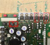
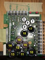
Here is the above board pic for reference.
In the mean time, let me digest your hand drawn schematic again.
I'll send you a pm as well.
Cheers,
Attachments

Last edited:
Hi Steve,
I learned that you are better at this stuff then I am.
continuing...
Then studying your schematic again this is not obvious to the layman.
Ignoring all the bottom of the board circuit protection parts (I think)
is trying to see how the round bridges feed the other part of the circuit.
Those are the VAC inputs to the bridges. The output of bridges in Vdc are
higher/lower and feed the vRegs through large smoothing caps. Then
regulated and each output is further smoothed by 3 smaller caps.
If I'm thinking correctly would this be the place where someone
would replace these three smaller caps with solid poly electrolytics?
Also, while I was meauring (I haven't started on the small caps)
All the large supply cap voltages seem to be close to the
cap rating. For example:
4 x 40V 1000 uF 35.4 Vdc
2 x 35V 5600 uF, 29.7 Vdc
2 x 63V 3900 uF, 45.6 Vdc
2 x 35V 4700 uF, 14.8 Vdc ***Check***
2 x 35V5600 uF, 29.9 Vdc
1 x 16V 15000 uf, 13.8 Vdc
Cheers,
Attachments
Last edited:
Yes, and these were the first four measurements I posted in the follow up post.I still think readings are encouraging but the AC magnitudes look suspiciously large.
I'm posting a new pic indicating the measurements (1 through 4) I was trying to specify.
1. 11.8 VAC round bridge rectifier.
2. 35.4 Vdc cap C4.
3. 53.8 VAC square bridge rectifier
4. 35.5 Vdc cap C6.
I was not aware they were suspiciously large. Not trying to be a smart ***. I just
don't have the experience to know if something is large or small relative to input or output.
Now, are those cap voltages also very large all things considered?
I've read, caps are more efficient when the voltages are closer to their design voltage
then way under the design voltage. I don't know if this is true or not.
Let me see if I can make a sim of it? That might take a while. I don't know
if I even have the required devices.
Last edited:
So what are the regulator outputs relative to the local grounds? Maybe there's some solace there.
Things are not making sense. What's the history of this unit? Has it been "worked on" by someone in the past? Can the connector wiring to the transformer(s) secondaries be trusted to be "factory original?"
Things are not making sense. What's the history of this unit? Has it been "worked on" by someone in the past? Can the connector wiring to the transformer(s) secondaries be trusted to be "factory original?"
Hi Steve, yes it can be trusted. It shows no signs of having been worked on in the past.
It was acquired from Motorola's liquidator when they were closing down their plants.
The other items I received had the latest firmware and all are still functioning.
Each flat cable is labeled for where it's connected. One is designated X12,
the other is designated X13. They have different widths and can only be
connected one way.
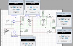
Interestingly I cannot get the sim to function properly.
I have two loads z1 pos and z2 neg.
Im measuring both caps and a big difference. Or maybe not,
they are in series.
I can't get the output voltages at the load Z2 to function, but LM7915 shows -15.612.
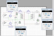
Two different configurations using multisim.
I also tried all three caps pointing downwards per schematic.
I think that was worse. Let me try moving them around again.
Its the same or do the pos side of caps need to connect to pos rail?
It was acquired from Motorola's liquidator when they were closing down their plants.
The other items I received had the latest firmware and all are still functioning.
Each flat cable is labeled for where it's connected. One is designated X12,
the other is designated X13. They have different widths and can only be
connected one way.
Interestingly I cannot get the sim to function properly.
I have two loads z1 pos and z2 neg.
Im measuring both caps and a big difference. Or maybe not,
they are in series.
I can't get the output voltages at the load Z2 to function, but LM7915 shows -15.612.
Two different configurations using multisim.
I also tried all three caps pointing downwards per schematic.
I think that was worse. Let me try moving them around again.
Its the same or do the pos side of caps need to connect to pos rail?
Attachments
Last edited:
Hi Sync,
There are very disconcerting mysteries here --- please don’t go replacing any caps until everything is better understood.
As a disclaimer, I’ll grant that my sketched schematic may not be accurate re the board. Would you please undertake the tedium of confirming its accuracy, especially near the two bridge rectifiers and their connection to C4 and C6? The topology I’ve shown makes perfect sense but is a bit unusual. (A more typical circuit would use a center-tapped transformer and a single bridge rectifier. Hence an earlier question about presence of any center-tapped secondaries.)
We need to confirm an accurate schematic so that we can discuss with confidence what’s being observed. For now let’s assume the sketch is correct.
I have to be very blunt about the simulation: the sim seems to present errors that make me distrust the simulator software program itself irrespective of the schematic. I could cite inconsistencies in the results it has presented, but that would be digression.
Again with the rash assumption of a satisfactory sketch, we don’t need simulation to know that things are not making sense:
11.8 V RMS implies a peak 16.7 V peak across the transformer secondary. This is not enough to produce the measured 35.4 VDC across C4.
Similarly, 53.8 V RMS implies 76 V peak applied to the bridge input clearly at odds with measured 35.5 VDC across C6.
As a further aside, the voltage across C4 and C6 seems inordinately large for 15 V regulators and uncomfortably near maximum operating voltage.
All these observations lead me to be suspicious of the transformer connections to the board. To allow bench testing of the PS board, might have you added “extension cables” that might be miss-wired?
There are several LT1086 regulators but I can’t make out the voltage version from the photos; probably 5V but please advise.
I believe these incongruities have to be resolved to make progress. I’ll help if I can.
Steve
There are very disconcerting mysteries here --- please don’t go replacing any caps until everything is better understood.
As a disclaimer, I’ll grant that my sketched schematic may not be accurate re the board. Would you please undertake the tedium of confirming its accuracy, especially near the two bridge rectifiers and their connection to C4 and C6? The topology I’ve shown makes perfect sense but is a bit unusual. (A more typical circuit would use a center-tapped transformer and a single bridge rectifier. Hence an earlier question about presence of any center-tapped secondaries.)
We need to confirm an accurate schematic so that we can discuss with confidence what’s being observed. For now let’s assume the sketch is correct.
I have to be very blunt about the simulation: the sim seems to present errors that make me distrust the simulator software program itself irrespective of the schematic. I could cite inconsistencies in the results it has presented, but that would be digression.
Again with the rash assumption of a satisfactory sketch, we don’t need simulation to know that things are not making sense:
Given the voltages reported in measurements 2 and 4, neither 1 nor 4 are sensible bridge input voltages:Originally Posted by SyncTronX
1. 11.8 VAC round bridge rectifier.
2. 35.4 Vdc cap C4.
3. 53.8 VAC square bridge rectifier
4. 35.5 Vdc cap C6.
11.8 V RMS implies a peak 16.7 V peak across the transformer secondary. This is not enough to produce the measured 35.4 VDC across C4.
Similarly, 53.8 V RMS implies 76 V peak applied to the bridge input clearly at odds with measured 35.5 VDC across C6.
As a further aside, the voltage across C4 and C6 seems inordinately large for 15 V regulators and uncomfortably near maximum operating voltage.
All these observations lead me to be suspicious of the transformer connections to the board. To allow bench testing of the PS board, might have you added “extension cables” that might be miss-wired?
There are several LT1086 regulators but I can’t make out the voltage version from the photos; probably 5V but please advise.
I believe these incongruities have to be resolved to make progress. I’ll help if I can.
Steve
Last edited:
Demian, Steve,
I don't have answers, but willing to keep investigating.
I'm wondering if the measurements are also picking up some inductance
from the transformers? But then they go through vRegs, so probably not.
NO, there are no extension cables etc. I'm using the original connections
that R&S used in the UPD. They are firmly locked into place on their connectors.
And, rest assured, I'm not about to go substituting parts into the board until
I have some answer if this is correct or not. Nothing like spinning ones wheels.
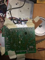
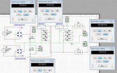
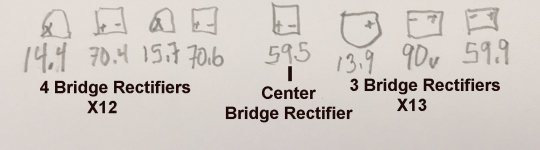
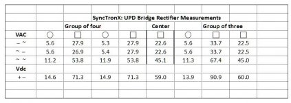
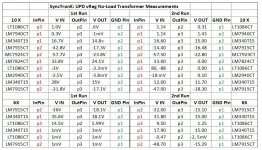
Here are the transformer measurements, 1st pass directly into disconnected connector and 2nd pass, connected to the power supply measured on the
soldered connection on the back of the board. Following that are are two sets of bridge rectifier measurements the first set last week and the second set
a day or two ago.
I'll get back later this afternoon or evening, burning daylight and I have to do
some home maintenance. Happy wife, happy life.
Cheers,
I don't have answers, but willing to keep investigating.
I'm wondering if the measurements are also picking up some inductance
from the transformers? But then they go through vRegs, so probably not.
NO, there are no extension cables etc. I'm using the original connections
that R&S used in the UPD. They are firmly locked into place on their connectors.
And, rest assured, I'm not about to go substituting parts into the board until
I have some answer if this is correct or not. Nothing like spinning ones wheels.
Here are the transformer measurements, 1st pass directly into disconnected connector and 2nd pass, connected to the power supply measured on the
soldered connection on the back of the board. Following that are are two sets of bridge rectifier measurements the first set last week and the second set
a day or two ago.
I'll get back later this afternoon or evening, burning daylight and I have to do
some home maintenance. Happy wife, happy life.
Cheers,
Attachments
Last edited:
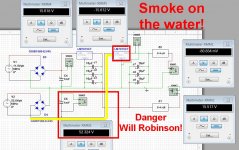
Demian,If you feed 53V negative into an LM7915 normally you get smoke. Please check that.
It's the sim and I might not have it set up correctly.
Any way, it reminds me of a tune. : )
Sorry, I couldn't help myself,
The devil made me do it.
Please see the attached Multisim with comments.
Cheers,
Attachments
Spike-
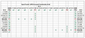
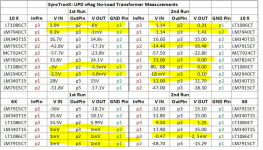
I marked the suspicious voltages on this version of your chart. Those all need to be reviewed because they do not make sense.
1) Are you checking the regulator voltages against their local ground or some common ground? I think there are 3 to 6 floating supplies that only interconnect on the analog boards. That could explain the 0v in measurements.
2) On the LT1086 can you check the associated resistor values that are programming them?
3) Measure the DC resistance across the output caps following their polarity. Any that are below 1K may point to a failed component.
4) Can you read the - number on the LM2940's? That would be the voltage set internally.
5) I always find it helpful to download the datasheets on the parts giving me trouble. it makes everything easier when you can see how they are used. I think only a few of the regulators are adjustable.
Attachments
Dittos to Demian's post above!
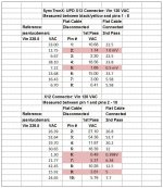
I'm not convinced that left hand table in post 55 has any real meaning. The readings may a function of inter-winding capacitance and have little significance.
What is the Black/Yellow wire you reference connected to? To help clarify the transformer configuration, would you test the designated cells for continuity in the matrix below? (I tried to save in Xcel file but Xcel won't cooperate
Attachments
I figured out that diyaudio prohibits Xcel file uploads but I can PM the file if you wish.
In the spreadsheet, I pasted the matrix arrays twice. My thinking is the first matrix will depict paths that show continuity. The duplicate matrix could then show the AC Volts produced at proven winding pin pairs.
In the spreadsheet, I pasted the matrix arrays twice. My thinking is the first matrix will depict paths that show continuity. The duplicate matrix could then show the AC Volts produced at proven winding pin pairs.
- Home
- Design & Build
- Equipment & Tools
- Rohde & Schwarz UPD: Troubleshoot then Restore to Glory