Here are the next group of measurements.
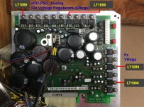
First Pic: The location of the Voltage Regulators (VRegs).
10x for those across the top.
6x for those along the side.
LT1086CT location is shown
Because it's hard to read them in the pics and in real life.
10x -- Order of measurement is shown from left to right.
6x -- Order of measurement is shown from top to bottom.
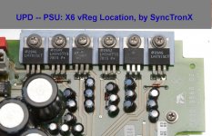
Second Pic: 6x easy to read VRegs (left to right same as top to bottom).
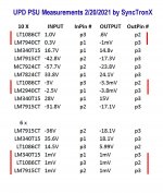
Third Pic: Shows the measurements made, Input, Output.
The red stripes shows the devices in question, low input and low output.
Now, it was late when I was taking these measurements, and probe tip
bridged the device as I turned to look at the HP34401A. Then I went
back again but got these readings.
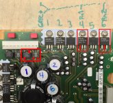
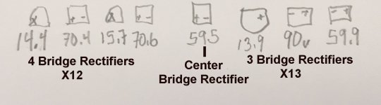
Forth Pic: I traced the input 4 and input 6 back to the bridge rectifiers
there to the square box.
VReg 4 goes through cap 4 to both the pos and neg
leads of the bridge rectifier.
VReg 6 goes through cap 6 to both the pos and neg
leads of the other bridge rectifier.
Now I'm having a brain fart on this.
No wonder there is not input nor output
as the input to each VReg is connected
to the pos and neg lead of the bridge rectifier.
However when I change swap leads
then the caps stop the continuity check and
the signal won't go through the caps.
So, the caps aren't open. Yet this power supply
doesn't pop fuses nor does it get hot.
I'll go back and measure by resistance and see if that reveals anything.
I'm not sure how to proceed?
I'm thinking desoldering the caps labeled 1,2,3,4.
I can check them first in circuit with my Dick Smith ESR meter
and if any look high, pull it and check it with my DER-EE 5000 LCR meter.
If one is bad, replace all four. see what that does.
Thinking if replacing those, what about the rest of this
power supply. 27 like small caps, 8 like small caps,
1 blue small cap and 9 large reservoir. These have all
exceeded their 1000 hours max temp lives I'm sure?
NOTE: I guess the posts from the other UPD thread got deleted instead of moved.
I have no idea where they are but they aren't here. I'll ask again.
Cheers,
First Pic: The location of the Voltage Regulators (VRegs).
10x for those across the top.
6x for those along the side.
LT1086CT location is shown
Because it's hard to read them in the pics and in real life.
10x -- Order of measurement is shown from left to right.
6x -- Order of measurement is shown from top to bottom.
Second Pic: 6x easy to read VRegs (left to right same as top to bottom).
Third Pic: Shows the measurements made, Input, Output.
The red stripes shows the devices in question, low input and low output.
Now, it was late when I was taking these measurements, and probe tip
bridged the device as I turned to look at the HP34401A. Then I went
back again but got these readings.
Forth Pic: I traced the input 4 and input 6 back to the bridge rectifiers
there to the square box.
VReg 4 goes through cap 4 to both the pos and neg
leads of the bridge rectifier.
VReg 6 goes through cap 6 to both the pos and neg
leads of the other bridge rectifier.
Now I'm having a brain fart on this.
No wonder there is not input nor output
as the input to each VReg is connected
to the pos and neg lead of the bridge rectifier.
However when I change swap leads
then the caps stop the continuity check and
the signal won't go through the caps.
So, the caps aren't open. Yet this power supply
doesn't pop fuses nor does it get hot.
I'll go back and measure by resistance and see if that reveals anything.
I'm not sure how to proceed?
I'm thinking desoldering the caps labeled 1,2,3,4.
I can check them first in circuit with my Dick Smith ESR meter
and if any look high, pull it and check it with my DER-EE 5000 LCR meter.
If one is bad, replace all four. see what that does.
Thinking if replacing those, what about the rest of this
power supply. 27 like small caps, 8 like small caps,
1 blue small cap and 9 large reservoir. These have all
exceeded their 1000 hours max temp lives I'm sure?
NOTE: I guess the posts from the other UPD thread got deleted instead of moved.
I have no idea where they are but they aren't here. I'll ask again.
Cheers,
Attachments
Last edited:
phofman,
Points very well taken sir.
Yes it is a top shelf unit. components and build quality are very high as well.
I'll keep is going as long as I can and it isn't costing and arm and a leg.
If it gets to that point, I'll part it out.
Recall the number one failing part in all instruments and all makes and
models is the electrolytic capacitor. It worth replacing them when needed.
So I'm going through that process now.
Then the other big thing would be the hard drive.
Hmm, SSD wouldn't be bad at all I'm thinking.
But not right now.
We'll see.
Cheers,
Found Section 4, TROUBLESHOOTING
UPDATE: Section 4 Troubleshooting.
Finally I found a manual with section 4 TROUBLESHOOTING.
This is the section that R&S feels they cannot provide to the end user--go figure.
So I'm off to get the battery, finish cleaning out the VGA card from the
paste, adheasive-sticky stuff that impregnated the board and the plug in
receptacle. Today we have sun and the snow is melted and power is on.
Cheers,
Attachments
I've been researching my text books to figure out how to test these Voltage Regulators (vregs, Regs, etc) in circuit so as not to destroy the power supply. I didn't find anything.
However Demian and I discussed some avenues where I could proceed with measuring
the Reg and checking verifying they work according to plan. What plan? Well there
isn't one, no documentation other then the collective US (Everyman) working together,
sharing knowledge, experience to try and figure it all out and move forward.
That's what I'm working on now.
Cheers,
If I were in your situation, at first I check the transformer output voltage, next check the rectifier diode by a tester, then the circuit. If your measurement is correct, the erroneous circuit has one or more burned parts or the heating transformer. To be frank, I suspect your measurement.
Last edited:
Sinja,
Thanks.
How did your UPD measurements go? It would be beneficial for Everyman to see someone else's measurements of a known working UPD.
We ALL need a known reference and test and measurement process so that anyone with
a UPD can follow along and check their measurements against known working UPDs.
We must ALL join together and use ALL our collective intelligence to identify, quantify
what these instruments need and measure.
Mainly because our dear friends as Rohde & Schwarz want us all to not maintain our
units even though they don't make them or support them any longer.
They have the toys and they are spoiled brats.
To further our collective experience both Marc and I have made and posted
measurements mine are in the following posts. Others got deleted when they
weren't moved properly or stuck in a different thread--hey it is what it is.
Post #13 in this thread shows the measurements I made at the connector
for the two transformers. Note these are raw numbers and the transformers are
only loaded to the analog power supply board. The first pic shows how I'm
measuring the transformer outputs. I don't think there is another way to do
it, but I'm open to suggestions.
Post #21 in this thread shows the measurements I made with the transformers plugged
into the analog power supply. Everything else was without a load on it other then
the vRegs and their various capacitors etc.
I show to which pins I affix the lead for the measurement.
and use the appropriate ground post on the analog power supply board.
I suppose I can measure them on the vReg ground pin instead of the
boards ground pin? Why? So I have an extra set of measurements?
or perhaps those are isolated from ground at that location?
therefore the ground should be measured with ground on the
actual vReg pin.
Both sets of measurements were made using a variac which shows 120 VAC in.
Voltage measurements were made with an Agilent/HP 34401A which had out of
date calibration, however these are typically stable and measurements have been
validated with the other two HP 34401As that I have. There was no significant
difference between these three Meters. That is, maybe a slight difference at the
5-1/2 or 6-1/2 digit, but not relevant for standard bench top measurements.
All three Agilent/HP 34401A show no errors, have the latest firmware etc.,
and come from a reliable, clean source, from a working lab, not from a
manufacturing floor which ten to be not as clean as the lab. In short, I trust their measurements.
Why do I say that? Because I have a few insturments from the manufacturing floor
and many were covered with unknown crap and needed heavy cleaning etc
to be fully functional.
So now that I've gotten that out of the way, how would you propose that Measure these
devices and the transformers again? How did your UPD measurements go? It would be
nice to see someone else's measurements of a known working UPD. You know Marc
and I could be the blind leading the blind. As Dr. Edwards Deming would say,
"you'll end up out in the Milky Way" on deviation.
and
"It's unknown and unknowable."
Really.
Cheers,
Last edited:
Sinja, That is ok if you suspect my measurement, because there is nothingIf I were in your situation, at first I check the transformer output voltage, next check the rectifier diode by a tester, then the circuit. If your measurement is correct, the erroneous circuit has one or more burned parts or the heating transformer. To be frank, I suspect your measurement.
else to go from; that is no known what are they supposed to read, right?
Except now you piqued my curiosity, what can I do differently in my
new set of measurements that I didn't do with my first set of measurements?
After looking at the data sheets again, I realized that I could circumvent
the ground tabs provided by R&S on the board and use the ground pin on the
Voltage Regulators (vRegs) themselves. This should give me a more
accurate measurement.
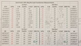
Here are the 2nd set of Bridge Rectifier and vReg Measurements.
I got to get back at it, let me know what jumps out at you?
The issues with the 10X set:
LT10086CT - Low inputet, Low Output
LM7940CT - Low Input, Low Output
LM7824CT - No Output
LT1086CT - No Input, No Output
LM2940CT - No Input, No Output
The issues with the X6 set:
LM1086CT Low Input, Low Output
LM1086CT No Input, No Output
What do we know:
The transformers are providing output voltage.
The bridge rectifiers are providing DC to the vRegs.
10X vRegs
LT1086CT - vReg have low input and low output why?
LM7940CT - vReg have low input and low output why?
LM7824CT - vReg has input but no output, why?
LT1086CT - vReg has low/no/fluctuating input and no output, why?
LM2940CT - vReg low/no/fluctuating input and low output, why?
6x vRegs
LT1086CT - vReg has low input and low output, why?
LT1086CT - vReg has lower (.4V) input and lower output, why?
NEXT STEP(S): I'll bgo back through these circuits and check their
diodes, caps and electrolytics caps with Dick Smith ESR meter.
Followed by providing an input voltage trough the caps to the various
voltage regulators observing cap charge rate, then voltage in
and out of the vReg.
Placing a directed input voltage to the vRegs with
current limited to 100mA. And see if I get output.
QUESTION:
In the mean time, would someone please break open their working UPD
and take some measurements for us diyAudio forumites?
We need to have some good known working references
as R&S won't provide them.
COMMENTS:
That is my plan, anyone following along please speak up and share
your thoughts on things.
Cheers,
Attachments
Last edited:
Spike-
When you say low input, low output is there a difference between the input and output voltage of the 3 term regulator? One nice aspect of three terminal regulators is that they are simple and you can see the ground reference and the in V and the out V the regulator is working with.
Another next step-
Are the loads connected? Can you power the analog supplies with the analog modules disconnected? Have you identified which supply connects to which module? The source module is most likely completely isolated from the chassis and same with the input/analyzer module. There may be 4 isolated supplies with the digital AD/DA stuff running independent of the analog processing.
If you can break down the system to manageable blocks and then test each block independently you can get it running. Time an patience. At least you know it once worked.
Yes.Spike-
When you say low input, low output is there a difference between the input and output voltage of the 3 term regulator?
For example, under 2nd Run, reading across the 10X, vRegs
LT1086CT (1ST)
Input pin3 is 1.14V
Output p2 is 0.305V
Gnd is pin 1.
LM7940CT (2nd down)
Input pin1 is 1.49V
Output p3 is 1.43V
Grd is pin 2.
Agreed.One nice aspect of three terminal regulators is that they are simple and you can see the ground reference and the in V and the out V the regulator is working with.
No loads connected. Yes, just the Analog Power Supply (APS)Another next step-
Are the loads connected? Can you power the analog supplies with the analog modules disconnected? Have you identified which supply connects to which module?
board shown. Mutha' board is removed for cleaning to get the grey slime/crud out from underneith the interface.
The APS connects through a flat cable to the SMPS in the center of the UPD I believe.
I imagine the APSy connects to the mother board and its plug in components, while the SMPS I think powers another board to which
the "Secret Sauce" modules are connected.
I think it is something like that. The analog power supplyThe source module is most likely completely isolated from the chassis and same with the input/analyzer module. There may be 4 isolated supplies with the digital AD/DA stuff running independent of the analog processing.
board is something I'm in the process of identifying which vReg(s)
go where. You've given me a thought, maybe I can trace the the
vRegs from their grounds also.
What is strange is that I can trace some of the vReg input pins
and output pins through their capacitors to the bridge rectifier.
And, it has continuity to both the bridge pos and bridge neg terminals.
It once worked. So I will get there eventually, time and patience.If you can break down the system to manageable blocks and then test each block independently
you can get it running. Time an patience. At least you know it once worked.
Reminds me of that song, "I get by with a little help from my friends."
Cheers,
Last edited:
Hi Sync,
I’ll offer a few suggestions.
First, Demian has offered great advice! It’s quite possible the some of the supply regulator sections are isolated from each other and are only joined at the destination modules; if this is the case, it’s possible your meter “ground” lead might be floating relative to regulator you’re testing.
I suggest making ohmmeter-continuity checks from the ground terminal of each IC regulator to all other three terminal regulator ground pins. Then you’ll know with certainty the grounding distribution scheme.
In like fashion, determine via ohmmeter which transformer secondaries have center taps. Presumably these drive bipolar filter supply capacitors.
I encourage sketching out a schematic of circuits that are causing trouble. These needn’t be works or art or detailed, but having a schematic often helps clarify.
I often tack-solder a convenient length of hookup wire to points-of-interest (eg. local ground). Then I can clip meter and/or scope ground to the wire, leaving one hand for probing and the other hand for board manipulation. (I sometimes resort to this practice to access circuit points within inaccessible modules.)
My personal preference is to probe with a scope—seems faster and often the displayed waveform is insightful.
Would you elaborate on this comment? Seems like it might be a useful clue---
Good luck!
I’ll offer a few suggestions.
First, Demian has offered great advice! It’s quite possible the some of the supply regulator sections are isolated from each other and are only joined at the destination modules; if this is the case, it’s possible your meter “ground” lead might be floating relative to regulator you’re testing.
I suggest making ohmmeter-continuity checks from the ground terminal of each IC regulator to all other three terminal regulator ground pins. Then you’ll know with certainty the grounding distribution scheme.
In like fashion, determine via ohmmeter which transformer secondaries have center taps. Presumably these drive bipolar filter supply capacitors.
I encourage sketching out a schematic of circuits that are causing trouble. These needn’t be works or art or detailed, but having a schematic often helps clarify.
I often tack-solder a convenient length of hookup wire to points-of-interest (eg. local ground). Then I can clip meter and/or scope ground to the wire, leaving one hand for probing and the other hand for board manipulation. (I sometimes resort to this practice to access circuit points within inaccessible modules.)
My personal preference is to probe with a scope—seems faster and often the displayed waveform is insightful.
What is strange is that I can trace some of the vReg input pins
and output pins through their capacitors to the bridge rectifier.
And, it has continuity to both the bridge pos and bridge neg terminals.
Would you elaborate on this comment? Seems like it might be a useful clue---
Good luck!
Last edited:
Hi Steve,
Thanks for the guidance. The far right pic in post # 21
show those two vRegs and where there is continuity
back to the bridge rectifiers. They are highlighted in red.
Yes, for those two it is a clue as their traces go through
the 4 & 6 capacitors.
I bought a LED flat panel lamp just so I could use it to
trace it through the power supply. I'll post some more
pics when I get a chance. If you zoom in you can see I marked traces
in red sharpie, that pic or a later pic. I still have other pics I need to process.
Cheers,
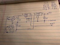
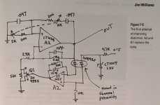
Hi Sync,
Please forgive the crude drafting and photography--- I bet even Bob Pease would be appalled!
Does the schematic look correct?
Assuming drawing is OK, then this is circuit not working???
Is there AC voltage across the inputs (~ to ~) of either of the two bridge rectifier modules?
Steve
Please forgive the crude drafting and photography--- I bet even Bob Pease would be appalled!
Does the schematic look correct?
Assuming drawing is OK, then this is circuit not working???
Is there AC voltage across the inputs (~ to ~) of either of the two bridge rectifier modules?
Steve
Attachments
Last edited:
Hi Steve,
Don't sell yourself short on that. It looks pretty good to me your schematic.
Had to pick up my little girl and run some errands after school.
I'll have to study it for a bit and compare with what I have etc.
But in general, your schematic looks pretty darn good. Now that you've
drawn it out I know what I'm supposed to do, how to draw them etc.
Let me give it a shot. Now I'm starting to understand the connections
and just those two parts actually make more sense now.
Steve, you've done this before! I had in my course work, but
it was nothing even that complex. Just the basics.
There are lots of other parts on the solder side of the board too
that isn't obvious from the top. Many SMD Caps, diodes, and
resistors. I think I have a few pics, I need to configure and will post
here or in the next post.
Time and Patience.... I will get there.
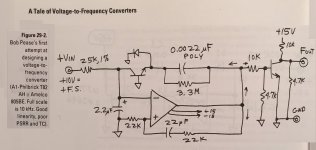
Well I think it is good, see what JW drew out and published.
Oh, on second thought, I think you might be right, Bob wasn't
to bad at drawing free hand was he?
Then to properly look at this board, I have a couple three other
pics that I put together for identification purposes. I'm not an
engineer, but trying to keep it logical. Some cap numbers are
omitted: 3,5,7,8,9. Then I numbered large caps in order of how
they are grouped, but at the bottom left, is the cluster Eff of caps.
I have to find a bottom side of the Analog Pwr Sup without
the light board to see all the SMDs.
Hopefully it will assist moving forward.
Cheers,
Post Script as many of you know, it takes time to set up and take pics,
then configure them for posting here. Moving ahead and hopefully documenting
it so that it will provide assistance to Everyman down the road if they encounter problems.
Don't sell yourself short on that. It looks pretty good to me your schematic.
Had to pick up my little girl and run some errands after school.
I'll have to study it for a bit and compare with what I have etc.
But in general, your schematic looks pretty darn good. Now that you've
drawn it out I know what I'm supposed to do, how to draw them etc.
Let me give it a shot. Now I'm starting to understand the connections
and just those two parts actually make more sense now.
Steve, you've done this before! I had in my course work, but
it was nothing even that complex. Just the basics.
There are lots of other parts on the solder side of the board too
that isn't obvious from the top. Many SMD Caps, diodes, and
resistors. I think I have a few pics, I need to configure and will post
here or in the next post.
Time and Patience.... I will get there.
Well I think it is good, see what JW drew out and published.
Oh, on second thought, I think you might be right, Bob wasn't
to bad at drawing free hand was he?
Then to properly look at this board, I have a couple three other
pics that I put together for identification purposes. I'm not an
engineer, but trying to keep it logical. Some cap numbers are
omitted: 3,5,7,8,9. Then I numbered large caps in order of how
they are grouped, but at the bottom left, is the cluster Eff of caps.
I have to find a bottom side of the Analog Pwr Sup without
the light board to see all the SMDs.
Hopefully it will assist moving forward.
Cheers,
Post Script as many of you know, it takes time to set up and take pics,
then configure them for posting here. Moving ahead and hopefully documenting
it so that it will provide assistance to Everyman down the road if they encounter problems.
Attachments
Last edited:
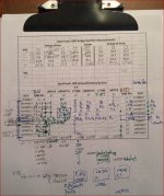
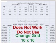
Here is the Bridg3 Rectifier data.
It's easier to read then my writng.
Now that I've checked the continuity between vRegs
its a mes and the table I though I could use doesn't work.
I also have to be very careful with the power supply, as I've
bent it around so many times some of the wires are beginning to
come part.
Here are two parts of it and I'll have to redo the bottom one.
Cheers,
Post Script - I take the constructivist approach to this, that is by putting the measurements together
in a chart or table--it helps me think about it and bring clarity to my thoughts. diyAudio is like
a living laboratory log book. As Everyman comes and goes, peruses data some stop and give
pointers, assist, observe, comment and we're all the better for it. It takes courage to show other
folks you don't know what your doing.
Einstein said it best, "If we knew what we were doing, it would not be called research."
Attachments
Last edited:
So, the UPD is designed logically.
The 10x vRegs are their own separate entity with at least two ground
structures. The two LT1086 vRegs are isolated from the other eight
vRegs in this row and they separate the grounding scheme of the
vRegs.
After the first LT1086, the next five vRegs share a common ground.
After the Second LT1086, the next three vRegs share a common ground.
AND
The Loan LM7824 has p2, p3 continuity with
the grounds of the first LM7940, LM340T15M, AND LM7915.
Somehow the MC7924 avoided this.
I think the LM7824 is fried. Now, what wen along with it?
And how to keep troublshooting with out breaking all the wires?
Then from the 6x vReg row it's similar.
The first LM7915 shares ground with LM340T15.
The first LT1086 I thought was isolated,but then there
are intermittents between pins. And now I can recall my messy
notes so I'll have to give you a resin check on this.
Maybe they aren't so similar after all.
I do know that reversing the leads has interesting effects.
On some of the devices, all the pins have continuity with all the pins of
two of the other vRegs.
cheers,
Last edited:
Spike-
Looking at the back of the circuit makes it much easier to follow. I think there are 7 bridge rectifiers. With some tracing you can then sort out which circuits connect to which grounds.
Are the DC volt numbers you show correct? The cap voltage ratings will give you a good clue. Expect the voltages to be around 1/2 the cap ratings. Those voltage are way higher than what you were seeing across the regulators.
Trace out one of each regulators local circuit. I suspect they are all about the same.
Then a map showing which regulator connects to which pin on the cable and which rectifier/cap.
This is pretty painful reverse engineering but at least this is a simple circuit. Also its very unlikely that more than 1 failed. Look for a common point of failure or something on the order of 240V in with it set to 120V. Or connection the wrong cables up. Usually difficult but can happen. Along with reversed cards. Why systems are still designed with connectors centered is beyond me. A simple offset would eliminate a lot of screwups.
Sync, I just had a minor brainstorm that may reduce the stress on all your connecting cables:
If I am summarizing correctly, your power supply board has a number of regulators (some dual positive/negative) and most are isolated with respect to each other. They are all linear three-terminal types, so they should behave properly without requiring added load resistance. I’m suggesting that you may not need to connect any cables other than the transformer powering the regulator section you’re debugging. Just make sure you’ve improvised a connection to the appropriate circuit common for your debugging. Once you have all regulators operating correctly, then you restore the cables to the destination boards.
I hope this idea works/helps.
Last edited:
- Home
- Design & Build
- Equipment & Tools
- Rohde & Schwarz UPD: Troubleshoot then Restore to Glory