I am starting this thread to discuss the techniques of measuring low distortion levels, say, 0.000 010% (10u%, -140dB) with inexpensive equipment such as a sound card.
The problem of measuring such low distortion levels came up in connection with developing an audio power amplifier with the loop gain of 100dB@20kHz and with the correspondingly low distortion levels even at the high end of the audio spectrum.
What I don't want to discuss is choosing (or making) a better sound card or a low distortion oscillator. These topics are very interesting but are being discussed in a number of other threads which I don't want to duplicate. Thank you for keeping these out of this thread. Having said this, I can confirm that the Linear Technology AN-67 low distortion oscillator built on PCBs from diyAudio member Frex works very well indeed.
Instead, I want to focus on the problems that arise when easily available equipment is used for assessing the distortion performance of highly linear amplifiers and on the way to address those problems.
So far, several topics are emerging:
- Properly conditioning the DAC output signal and the ADC input signal
- Using (passive) filters to filter out the distortion of the DAC and to remove the fundamental from the ADC input
- Subtracting the scaled output signal from phase corrected input in either analog or digital domain
- Increasing the noise gain of the device-under-test to increase distortion to a measurable level and estimating from it the distortion under normal conditions
- Correcting nonlinearities of the DAC and ADC in the digital domain (the work of phofman)
Last edited:
The most straightforward way requires some external hardware. You would need an ultra low distortion source or passive low pass filter for your source to remove the remaining harmonics of the source. Then a passive notch connected to your sound card. Finally some good software to make sense of what you see. I recommend DiAna DiAna, a software Distortion Analyzer because it can give you a lot of good insight into the source of the distortions.
The passive networks will have much lower intrinsic distortion and have been used for this for at least 50 years. You will also need a soundcard with enough bandwidth to see the harmonics of the 20 KHz signal. A 192 KHz card will show HD2, HD3 and HD4. A different option is a digital scope/USB scope with decent FFT capabilities. With the passive filter even an 8 bit scope can have decent resolution on the harmonics.
There are threads here that have touched on everything above except a low pass filter for a source like a soundcard.
Subtracting the input signal from the output with the right ratio, as in QUAD's subtractive tests or Bob Cordell's distortion magnifier, could also help. Besides, there are phofman's experiments with sound card distortion cancelling by digital predistortion:
Digital Distortion Compensation for Measurement Setup
Digital Distortion Compensation for Measurement Setup
Hi there,
I have always wondered if we (here) could copy a technique used by some low-distortion OpAmp manufacturers such as TI, which fundamentally fool the amp/circuit into making it's distortion components appear more magnified at its output.
For example, if you look at the TI LM4562 opamp datasheet page 23, they use a 100 ohm resistor between the inverting and non-inverting inputs to effectively magnify the distortion component by 101 times. If someone more experienced at low distortion design that I am could turn that into a generalised model it that might help. So that may give you a 20dB advantage.
I would think that to get down to the level of measurement you suggested, you are going to have to add a further technique (in addition) such as a notch filter/low-noise amp and/or Bob Cordell's Distortion magnifier.
Kind regards
Mike
Those are all great solutions but none are particularly simple to implement from scratch.
True, but who would think measuring -140 dB distortion levels with a sound card would be easy?
I have always wondered if we (here) could copy a technique used by some low-distortion OpAmp manufacturers such as TI, which fundamentally fool the amp/circuit into making it's distortion components appear more magnified at its output.
For example, if you look at the TI LM4562 opamp datasheet page 23, they use a 100 ohm resistor between the inverting and non-inverting inputs to effectively magnify the distortion component by 101 times. If someone more experienced at low distortion design that I am could turn that into a generalised model it that might help. So that may give you a 20dB advantage.
That's also not straightforward because with 100 dB of loop gain at 20 kHz, the thread starter's amplifier is almost certainly conditionally stable, so such tricks could make it oscillate.
For example, if you look at the TI LM4562 opamp datasheet page 23, they use a 100 ohm resistor between the inverting and non-inverting inputs to effectively magnify the distortion component by 101 times. If someone more experienced at low distortion design that I am could turn that into a generalised model it that might help. So that may give you a 20dB
Mike
What you achieve is reduced loop gain, reduced feedback and accordingly increased distortion. This gives you an idea how low your distortion maybe with full neg feedback - but in fact this is a theoretical assumption instead of a real measurement.
Thank you all for the great responses and pointers/links! I see three themes:
- Using (passive) notch and low pass filters. I have done some work with these and will share my experience.
- Subtracting phase corrected input signal from scaled output. I have some experience with Cordell’s distortion magnifier which uses a first order low pass filter for phase correction and works well with dominant pole compensated amplifiers. I have seen others doing the same with conditionally stable amplifiers but never got into details - will be interesting to develop this into a practical recipe.
- Increasing noise gain to get distortion to the level that can be directly measured. Will have to look into how this would affect the amplifier’s compensation.
If the amplifier has a response that extends all the way to DC and a single-loop frequency-independent feedback network (no phantom zero/lead compensation in the feedback), then phase compensation becomes really easy: you won't need any over the frequency range where the amplifier has a huge loop gain.
That's a good point, thank you! The feedback network is frequency dependent; it has a pole at 45kHz and three zeros at high 100s of kHz. Since the zeros are much higher than any frequency of interest, however, maybe it is still possible to use Cordell's approach and correct phase just for the pole?no phantom zero/lead compensation in the feedback
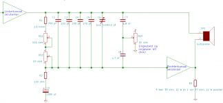
For what it's worth, for an amplifier with second-order Butterworth roll-off below 1 Hz and above 140 kHz, I could get about 60 dB of suppression of a music signal (Tracy Chapman, Matters of the heart) with the attached correction network.
Attachments
Last edited:
If a very clean sine signal synchronous to the ADC sampling clock is available, it can be used to measure/calibrate distortion profile of the ADC input at signal level equal to output of the DUT. The ADC distortion profile can be compensated in software, allowing the much smaller DUT distortions to appear. IME a decent soundcard can measure a modern opamp THD without any artificial distortion magnification or notch filtering (excluding the very best general-purpose models if using distortion-compensated DAC output, not a clean analog oscillator).
But IME it requires a dedicated measurement adapter with output buffer output powerful enough not to change distortion when connected to the calibration loopback and the DUT input, an input buffer close to the DUT and the calibration loopback to minimize effects of the input cables capacity, the level-calibration circuitry, and proper software processing.
The DAC output can have its distortion measured and compensated to a large extent. But for the miniscule THDs mentioned in the original post IMO a very clean analog oscillator synchronized to DAC output (= same clock as ADC) would be required.
Thank you. I glanced through your thread last night and understood the basic idea of correcting ADC nonlinearity in software. The results are very cool but the details of implementation do seem to be quite involved. Also, I am not familiar with Linux enough to follow step-by-step instruction but not enough to be comfortable. Digging into it would be a separate project to which I might come back when other lines are explored.
In fact, before correcting ADC nonlinearity, there is much of very, very basic stuff that needs to be covered, such as signal conditioning.
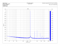
I am using an E-MU 0204, an obsolete but still decent sound card with AK5385 ADC and (I believe) AK4396 DAC.
The card's specs are 113dB SNR and 0.0008% THD. In practice, is shows a bit better THD, around 0.00067% (-103dB), when its output is directly connected to the input and the level is set at -6dBFS (about 1Vrms):

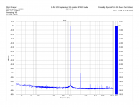
However, when input is connected to the output via a 33k resistor (this is relevant because the output impedance of, say, a passive filter can be quite high), THD grows by more than 20dB to 0.0088%:

Looks like a textbook case of common mode distortion. A glance at the schematic of the ADC front end (found on the web) confirms the suspicion. Both U4 and U5 should see a low impedance source:

The fix is to buffer the input by something not susceptible to CM distortion. One easy (but expensive) option is an OPA627 connected as a unity gain buffer. The OPA627 features a bootstrapped cascode in the first stage and is comfortable with high impedance sources. With it, the distortion is actually a couple of dB better than with a straight wire:

I am using an E-MU 0204, an obsolete but still decent sound card with AK5385 ADC and (I believe) AK4396 DAC.
The card's specs are 113dB SNR and 0.0008% THD. In practice, is shows a bit better THD, around 0.00067% (-103dB), when its output is directly connected to the input and the level is set at -6dBFS (about 1Vrms):
However, when input is connected to the output via a 33k resistor (this is relevant because the output impedance of, say, a passive filter can be quite high), THD grows by more than 20dB to 0.0088%:
Looks like a textbook case of common mode distortion. A glance at the schematic of the ADC front end (found on the web) confirms the suspicion. Both U4 and U5 should see a low impedance source:
The fix is to buffer the input by something not susceptible to CM distortion. One easy (but expensive) option is an OPA627 connected as a unity gain buffer. The OPA627 features a bootstrapped cascode in the first stage and is comfortable with high impedance sources. With it, the distortion is actually a couple of dB better than with a straight wire:
Attachments
Last edited:
Alex
Have you any ideas about what source (oscillator) would be necessary in order to give a pure and stable input to the device under test for such low levels of distortion. Using conventional thinking, it would have to be better than the measurement technique by about 10dB. I think that the best we have so far in the analogue world, is Viktor's oscillator.
Kind regards
Mike
ULDO and "Nacho" Oscillator and Notch Filter
I've been working on a low distortion oscillator and notch filter to assist measurements using a sound card.
My interests require both single-ended and balanced measurements and I wanted performance equal to or greater than what Vicktor has been able to achieve.
Two additional goals included using low-cost op amps and VCA stabilization.
The oscillator is based on Vicktor's work using a subtractive degenerated VCA operating at very low level instead of a FET. Composite op amps originally published by "cxb00463" provide additional open gain at the 1 KHz operating frequency that would be unattainable by op amps alone.
The notch filter is a balanced implementation (or dual SE) based on Jansek.
With the oscillator driving +20 dBu into a 604Ω load I've been able to get THD around -142 dBc, 0.00000757% or 0.075 ppm. At levels below that distortion drops into the measurement noise floor.
The oscillator and notch filter are still a work-in-progress. The oscillator is here: Super Low Distortion Ultra Pure Audio Oscillators Revisited - Page 8 - Pro Audio Design Forum
The notch filter here: Super Low Distortion Ultra Pure Audio Oscillators Revisited - Page 12 - Pro Audio Design Forum
And some distortion measurements of the oscillator: Super Low Distortion Ultra Pure Audio Oscillators Revisited - Page 9 - Pro Audio Design Forum
The thread begins with a survey of some of the work done previously with contributions from Hood, Cordell, Bateman, Williams, Eager, Mickevics, Jansek et al.
Super Low Distortion Ultra Pure Audio Oscillators Revisited - Pro Audio Design Forum
- Status
- This old topic is closed. If you want to reopen this topic, contact a moderator using the "Report Post" button.
- Home
- Design & Build
- Equipment & Tools
- Measuring low distortion levels with a sound card