Hi,Hi KSTR,
By using mercury wetted reed relays for the multiplexer, I didn't have serious issues with switching time and bouncing. It reduced the "play load" by a mere 2%.
But that's not all. Apart from measuring the distortion of the Ref and DUT on a interleaving basis, I also measured the frequency and phase response of both of them (also interleaving). That reduced the "play load" by another 50%. In other words, that doubles the total measuring time, which was already quite long (1 hour or so in order to average out the noise sufficiently).
Now, almost 10 years later, I have abandoned this route and try to get the same measurement floor (-170dB) by using only passive twin T filters. Way more simple and less expensive. The only draw back of this approach is that you need to adapt the filters each time you change the fundamental frequency (measuring the distortion of an amp at only one frequency is not enough, at least at 20Hz, 1kHz and 20kHz).
BTW, what measurement floor you are aiming for?
Cheers,
E.
I'm aming at some 30dB below the analog noise floor of the RME and want to be able to extract a precision residual of arbitrary signals, not only for analysis but also for just plain simple listening. When the payload signal is a sine or simple IMD sequence of enough length, block averaging of that sub-section should be able to get another 10..20 dB but of course I might be running into process stability floor brickwalls by then.
With the long payloads I'm using currently with only 100 averages, dynamic gain drift with 1/f-character is a limiting factor for the measurement floor, the NULL-test residual is dominated by an AM-modulated version of still rather linear copy of the original.
But it's good enough already to nicely expose the error difference when switching the RME's analog reference level from +13dBu to +19dBu which changes gain or even bigger parts of the circuit (with standard opamp configs, no composites at work -- guessing here, of course).
In a simple THD or IMD loopback FFT measurement with REW it's not easy at all to find distortion differences and let alone judge what they actually do to signals.
I also could expose the (larger) error of the DAC-->ADC chain itself, compared to the original digital file which is actually harder as there is a lot of transfer function delta (AC coupling, DAC+ADC passband ripple and stropband transition).
At these error levels all of this might be nuts because it's possibly way below any reasonable thesholds of hearing but then again it does provide insight plus it's a fun exercise...
Last edited:
Making very small distortions/errors audible with music signals. Some examples. | Audio Science Review (ASR) ForumBefore that, I will post some latest results...
Most soundcards have rising noise floor above 40kHz so it does not make much sense to use 90kHz bandwidth. For 20kHz THD measurements a 60kHz low pass should do.
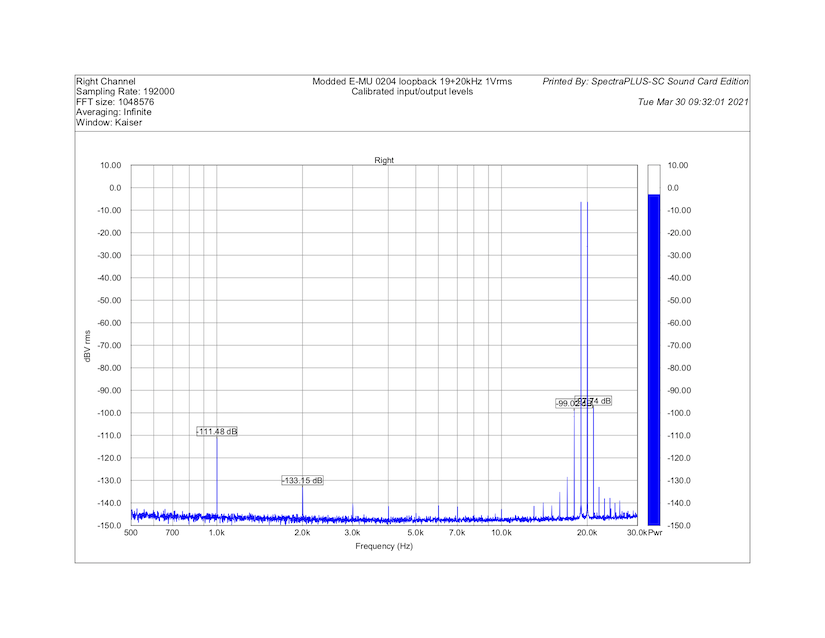
Of the several soundcards I have tested surprisingly the 15+ years old M-Audio ProFire 610 has the best high frequency performance (attached is loopback @20kHz). But unfortunately Win10 drivers for M-Audio ProFire (or Firewire add-on cards) are not that great.
Of the several soundcards I have tested surprisingly the 15+ years old M-Audio ProFire 610 has the best high frequency performance (attached is loopback @20kHz). But unfortunately Win10 drivers for M-Audio ProFire (or Firewire add-on cards) are not that great.
Attachments
Measuring 19+20KHz IMD
One way to avoid the rising noise floor at above-audio-range frequencies is to measure intermodulation instead of THD. Back in 1981, Bob Cordell published a paper discussing this. With IMD measurement, the requirements to the oscillator (or DAC) are relaxed, as the harmonics of the test signal are out-of-band. The IMD measurements have their limitations and are not easily converted to THD numbers, but they can be a useful guidance in comparing the linearity of various devices.
First try is with the sound card by itself.
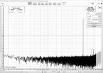
The performance of my E-MU 0204 on 19+20kHz test with its output connected with the input by a wire is not fantastic:
Halving the signal level helps somewhat:

Connecting the device-under-test with a low-impedance divider instead of the wire doesn't change the results appreciably:

Although one can make judgements on the linearity of the amplifier with this measurement, it does not seem very reliable.
One way to avoid the rising noise floor at above-audio-range frequencies is to measure intermodulation instead of THD. Back in 1981, Bob Cordell published a paper discussing this. With IMD measurement, the requirements to the oscillator (or DAC) are relaxed, as the harmonics of the test signal are out-of-band. The IMD measurements have their limitations and are not easily converted to THD numbers, but they can be a useful guidance in comparing the linearity of various devices.
First try is with the sound card by itself.
The performance of my E-MU 0204 on 19+20kHz test with its output connected with the input by a wire is not fantastic:
Halving the signal level helps somewhat:
Connecting the device-under-test with a low-impedance divider instead of the wire doesn't change the results appreciably:
Although one can make judgements on the linearity of the amplifier with this measurement, it does not seem very reliable.
Attachments

Using notch filters for IMD measurements
Since the sound card by itself does not produce very revealing measurements, second try is with notch filters.
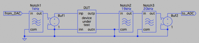
The measurement setup is as follows:
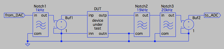
The first notch suppresses the 1kHz intermodulation produced by the DAC. The notch is followed by a buffer with low output impedance to drive the device-under-test (DUT).
The DUT is followed by two more notches that filter out the 19kHz+20kHz test signal. (I experimented with just one, tuned to 19.5kHz, but got better results with two.) The filters are followed by another buffer to avoid extra distortion in the sound card's front end as described in post #16.
All notches use Hall topology (post #25). I use discrete buffers, but OPA627 connected as unity gain buffer would work equally well.
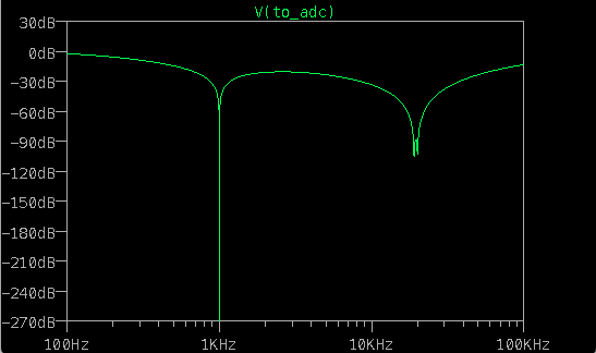
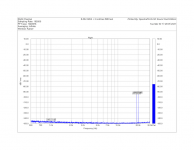
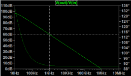
The simulated frequency response of the measurement setup:
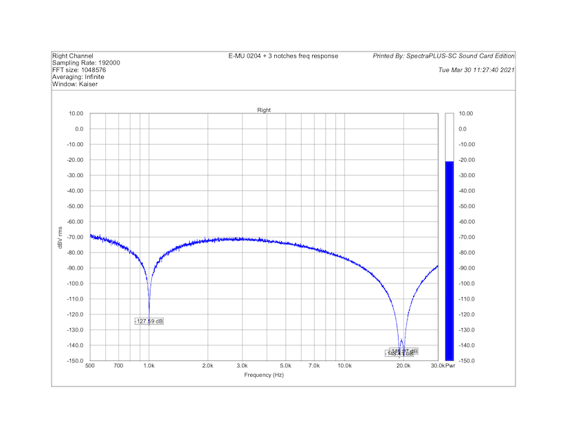
and the same from actual hardware:
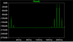
With the notch filters, the IMD of a straight wire looks acceptable (note that the levels at 19 and 20kHz are lower than actual due to the suppression by the notch filters):
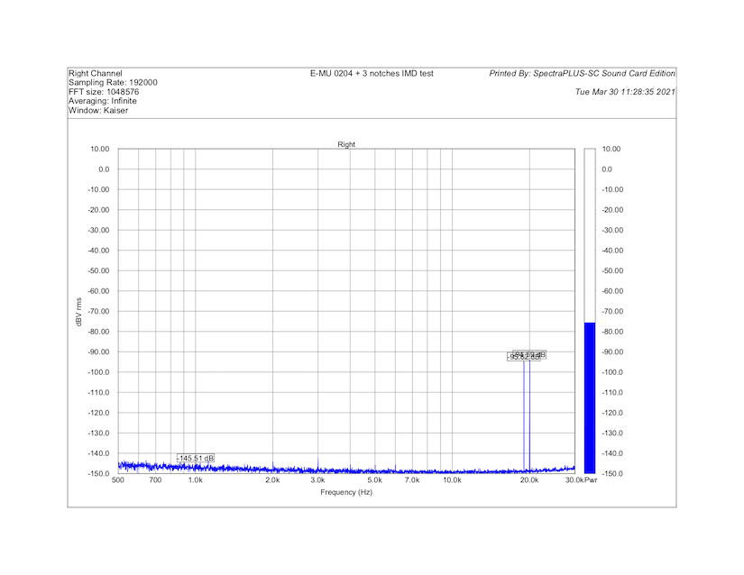
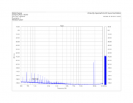
and the IMD level of the amplifier under test is now visible:

Here, the levels are calibrated to reflect the real voltages and DUT is followed by a -10dB resistive attenuator. That is, the peak at 1kHz is -123dBV (about 700 nanovolt) RMS. Not bad for an old sound card and a handful of easily available components on a solderless breadboard!
Since the sound card by itself does not produce very revealing measurements, second try is with notch filters.
The measurement setup is as follows:
The first notch suppresses the 1kHz intermodulation produced by the DAC. The notch is followed by a buffer with low output impedance to drive the device-under-test (DUT).
The DUT is followed by two more notches that filter out the 19kHz+20kHz test signal. (I experimented with just one, tuned to 19.5kHz, but got better results with two.) The filters are followed by another buffer to avoid extra distortion in the sound card's front end as described in post #16.
All notches use Hall topology (post #25). I use discrete buffers, but OPA627 connected as unity gain buffer would work equally well.
The simulated frequency response of the measurement setup:
and the same from actual hardware:
With the notch filters, the IMD of a straight wire looks acceptable (note that the levels at 19 and 20kHz are lower than actual due to the suppression by the notch filters):
and the IMD level of the amplifier under test is now visible:
Here, the levels are calibrated to reflect the real voltages and DUT is followed by a -10dB resistive attenuator. That is, the peak at 1kHz is -123dBV (about 700 nanovolt) RMS. Not bad for an old sound card and a handful of easily available components on a solderless breadboard!
Attachments


Last edited:
I suspect that there's a problem with using notches to suppress the IMD test signal. If i look at the suppresion of the two notches (graph 3) there seems to be around 40dB suppression for 18kHz for example which will eliminate the IMD sidebands from your measurements.
Relying on the 1kHz difference signal is not sufficient as this will only be generated for asymmetrical distortion mechanisms.
Relying on the 1kHz difference signal is not sufficient as this will only be generated for asymmetrical distortion mechanisms.
around 40dB suppression for 18kHz for example which will eliminate the IMD sidebands from your measurements
Correct. The above approach eliminates the 18 and 21 kHz intermodulation products and leaves only the 1kHz peak, which indeed is generated by asymmetrical distortion.
Actually, there is a problem even with 1kHz. Intermodulation products (as any other errors) are attenuated by feedback by a factor approximately equal to to the loop gain. In the usual case where the loop gain falls as frequency increases, lower frequency intermodulation products get attenuated more than those at higher frequencies. This can be quite dramatic in case of high loop gain amplifier - e.g. if the loop gain at 1kHz is 140dB, feedback reduces the 1kHz product by a factor of 10 million, which makes it difficult to measure. Back to square one.
It is sometimes suggested that a better test is 20kHz THD. I disagree, as it puts every harmonic outside of the audio band, where the distortion performance is neither required nor guaranteed. In particular, with high loop gain amplifiers, one wants to keep the loop gain high in the audio band, then drop it quickly as the frequency increases past 20kHz and close the NFB loop at the lowest possible frequency while maintaining phase margin / stability and an adequate impulse response. This calls for a rapid fall in the loop gain beyond 20kHz, which leads to higher 20kHz THD.
Nevertheless, there are two ways to address both problems simultaneously. First, there are other ways to reduce the level of test signal / fundamental before the ADC and thus minimize the ADC distortion; I will post on that separately.
Second, one can choose a different set of frequencies for the IMD test in order to push the products of both symmetric and asymmetric distortion (i) away from the fundamental; (ii) closer to each other; and (iii) closer to the upper limit of the audio band, in order to reduce the effect of both notch filters and loop gain. For example, one can combine three sines in the test signal, as Bob Cordell did in his paper, but choose the frequencies so that the products are grouped around 20kHz rather than 1kHz. But I like the simple combination of 7kHz and 13kHz sines, which produce an even-order IMD product at 7+13=20kHz and odd-order, at 13+13-7 = 19kHz. In addition, the 3rd harmonic of 7kHz is at 21kHz.
Some real-world measurements are to follow.
Actually, there is a problem even with 1kHz. Intermodulation products (as any other errors) are attenuated by feedback by a factor approximately equal to to the loop gain. In the usual case where the loop gain falls as frequency increases, lower frequency intermodulation products get attenuated more than those at higher frequencies. This can be quite dramatic in case of high loop gain amplifier - e.g. if the loop gain at 1kHz is 140dB, feedback reduces the 1kHz product by a factor of 10 million, which makes it difficult to measure.
Is that correct? That would mean that the IMD 1kHz product in open loop would be larger than the 19 & 20k test tones. That seems odd.
Jan
Is that correct? That would mean that the IMD 1kHz product in open loop would be larger than the 19 & 20k test tones. That seems odd.
Jan
Not sure I follow. Say, you have an amplifier with 1% open loop distortion (output referred) and 140dB open loop gain (for simplicity, flat in the frequency range of interest). You apply 100% feedback (e.g. connect the inverting input to the output, thus making it a unity gain follower - let's assume it is stable). Your loop gain is then 140dB. The distortion at the output will be attenuated by 140dB and will measure 1%/1e7 = 0.1u%. With a reasonable voltage level, say 10V RMS, that's 10 nanovolt and is difficult to measure. But the IMD 1kHz product in open loop still is 1% of the output.Is that correct? That would mean that the IMD 1kHz product in open loop would be larger than the 19 & 20k test tones. That seems odd.
Why not? The level of 1kHz product, open loop, may depend on frequency all right. But once it is generated, it is just another source of error correctable by NFB. Am I missing something?once generated there's no way that any amount of NFB at 1kHz will reduce it again.
Here is an example.
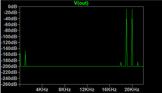
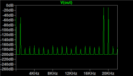
Let me take an amplifier with 1% open loop distortion, purely second order harmonic, and feed it with a 19+20kHz test signal:
In the output spectrum we observe, naturally, a -40dB (1%) peak at 1kHz:

The forest of peaks at other frequencies are just calculation artifacts.
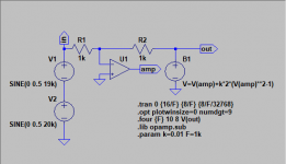
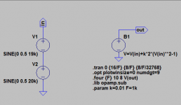
Now place the distorting amplifier in an NFB loop with 100dB of loop gain at DC:

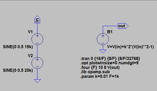
U1 is an ideal single-pole opamp. In the simulation, we can manipulate its gain-bandwidth product (GBWP) and thus change the loop gain at 19/20kHz relative to that at 1kHz. The simulation model is attached.
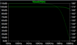
First, let me make GBWP very high, so that the loop gain at 19/20kHz and at 1kHz is very close to 100dB:

This, predictably, attenuates the 1kHz by 100dB, to -140dB:
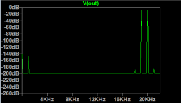
Now, let me make GBWP so that the loop gain at 1kHz is still about 100dB, but at 19/20kHz it is reduced to 87.5dB:
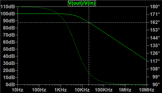
The intermodulation products at 18 and 21 kHz are now higher, but the peak at 1kHz is unchanged:

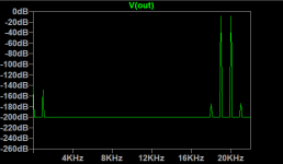
Finally, let me reduce the GBWP so that the loop gain at 1kHz is reduced to 60dB:

This increases both 1kHz and 18/21kHz products:

Clearly, the loop gain available at 1kHz affects the amplitude of the 1kHz intermodulation product. On the other hand, the loop gain at 19/20kHz has no effect at 1kHz, at least as long as the loop gain is high enough to attenuate secondary effects.
Let me take an amplifier with 1% open loop distortion, purely second order harmonic, and feed it with a 19+20kHz test signal:
In the output spectrum we observe, naturally, a -40dB (1%) peak at 1kHz:
The forest of peaks at other frequencies are just calculation artifacts.
Now place the distorting amplifier in an NFB loop with 100dB of loop gain at DC:
U1 is an ideal single-pole opamp. In the simulation, we can manipulate its gain-bandwidth product (GBWP) and thus change the loop gain at 19/20kHz relative to that at 1kHz. The simulation model is attached.
First, let me make GBWP very high, so that the loop gain at 19/20kHz and at 1kHz is very close to 100dB:
This, predictably, attenuates the 1kHz by 100dB, to -140dB:
Now, let me make GBWP so that the loop gain at 1kHz is still about 100dB, but at 19/20kHz it is reduced to 87.5dB:
The intermodulation products at 18 and 21 kHz are now higher, but the peak at 1kHz is unchanged:
Finally, let me reduce the GBWP so that the loop gain at 1kHz is reduced to 60dB:
This increases both 1kHz and 18/21kHz products:
Clearly, the loop gain available at 1kHz affects the amplitude of the 1kHz intermodulation product. On the other hand, the loop gain at 19/20kHz has no effect at 1kHz, at least as long as the loop gain is high enough to attenuate secondary effects.
Attachments
-
 schematic.png10.5 KB · Views: 576
 -
 Bode1.png12.3 KB · Views: 585
 -
 Bode0.png10.3 KB · Views: 577
 -
 schematic0.png9.8 KB · Views: 576
 -
 fft1.png10.1 KB · Views: 560
 -
 Bode2.png13 KB · Views: 567
 -
 fft3.png9.7 KB · Views: 552
 -
 bode3.png13.7 KB · Views: 550
 -
 fft4.png8.7 KB · Views: 553
 -
where does the loop gain matter.asc1.3 KB · Views: 44
Last edited:
Alexcp: I like your use of the chebyshev polynomial for the distortion. Looking at your formula - should it not be k*(2*V(in)**2 - 1) ?
IME the chebyshev polynomials scale correctly only for signals with max. amplitude exactly 1. Also the scaling did not seem to work correctly for multitone signals nonlinear-compensation/run_distortion.m at master * pavhofman/nonlinear-compensation * GitHub - maybe again due to amplitudes of individual tones not being equal to 1. IME if these conditions were not satisfied, the correct distortion was introduced, but its magnitude did not correspond to the k factor. But I may have overlooked something.
IME the chebyshev polynomials scale correctly only for signals with max. amplitude exactly 1. Also the scaling did not seem to work correctly for multitone signals nonlinear-compensation/run_distortion.m at master * pavhofman/nonlinear-compensation * GitHub - maybe again due to amplitudes of individual tones not being equal to 1. IME if these conditions were not satisfied, the correct distortion was introduced, but its magnitude did not correspond to the k factor. But I may have overlooked something.
Yes, you're right - thank you for catching this! That is a trigonometric identity: sin(x)^2 == (1 - cos(2x))/2. I was playing with different amplitudes and messed up the DC cancellation. And yes, you're right, with a different amplitude, both DC cancellation and H2 scaling are affected. Still, it works for illustration purposes.Looking at your formula - should it not be k*(2*V(in)**2 - 1) ?
That is what I'm doing here, really - two heads are better than one.Discussed it yesterday with a friend
Last edited:
")
- Status
- This old topic is closed. If you want to reopen this topic, contact a moderator using the "Report Post" button.
- Home
- Design & Build
- Equipment & Tools
- Measuring low distortion levels with a sound card