Also, There's _no_way_ I'll get away without using a coarse/fine pot setup for voltage. I've got a 3 turn wirewound pot connected, and it's such a ridiculously delicate adjustment.
I find that if a coarse/fine adjustment is properly implemented, it's actually a step better than a 10 turn pot, strangely enough. The trick is to use wirewound pots, then make the fine adjust *very* fine. With that setup I had no problem getting my old supply (which used modified Power One Linear supplies) set to 15.000 volts without excessive fiddling.
Accurate voltage dividers with temperature
Given that I'm doing another PCB, I thought it might be an opportunity to revisit some of the design decisions.
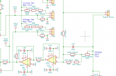
A key component of getting good voltage accuracy is being able to accurately sample the output voltage.
At present that's done with a resistive divider comprising a 1K 5ppm resistor on one side and a 19K resistor on the other side, giving me divide by 20. Getting some adjustability into that for calibration is where things get tricky. I used a pair of 10K 5ppm resistors in series for the 19K side, and added a trimpot across that so I could set that to 19K. The normal Bourns 3296 has a TC of 100ppm though, so in order to ensure it doesn't affect things badly as things heat and cool down, I use a 10K one in series with a 374K fixed resistor, so I can adjust the 19K side from 19.01K down to 18.98 (ie naff all adjustability). In practice it's only barely enough - the pot needs to be adjusted all the way to one end.
So I found cooler pots. Vishay Precision do drop-in replacement for the Bourns 3296, with 20ppm TC. I can only get it in 10K or 500Ω though, so I came up with the schematic below. 1K side unchanged, and a series/parallel network comprising the 2 x 10K 5ppm resistors in series, with a 300Ω 50ppm resistor across them for 18.75K, then a 500Ω 20ppm pot in series to allow me to set that from 18.75 to 19.25. A much better amount of variation, and because the trimmer is 20ppm, that shouldn't matter.
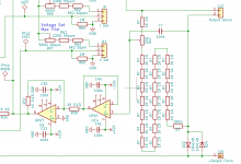
But then I got to thinking about ratiometric instead. The voltage set works with a 100ppm pot because it's a ratio on the same pot. The absolute value doesn't matter, as long as the whole pot changes at the same TC. These little Vishay Precision trimmers are a $20 part. Wouldn't it be nice if I could do everything ratiometrically for the voltage sense, then I could use cheap 50ppm parts entirely. So the second schematic shows that. 20 x 1K 50ppm resistors, with a 20Ω 100ppm pot between resistors 1 and 2. I ad 180Ω on the end of the 19K side to account for the pot. All the resistors are now 10c ones, plus a $3 pot, so it should be a lot cheaper, yet because the resistors can come from the same reel, it should be super-duper accurate, and track with temp nicely.
Or at least that's the plan. Is there anything I'm missing?
Given that I'm doing another PCB, I thought it might be an opportunity to revisit some of the design decisions.
A key component of getting good voltage accuracy is being able to accurately sample the output voltage.
At present that's done with a resistive divider comprising a 1K 5ppm resistor on one side and a 19K resistor on the other side, giving me divide by 20. Getting some adjustability into that for calibration is where things get tricky. I used a pair of 10K 5ppm resistors in series for the 19K side, and added a trimpot across that so I could set that to 19K. The normal Bourns 3296 has a TC of 100ppm though, so in order to ensure it doesn't affect things badly as things heat and cool down, I use a 10K one in series with a 374K fixed resistor, so I can adjust the 19K side from 19.01K down to 18.98 (ie naff all adjustability). In practice it's only barely enough - the pot needs to be adjusted all the way to one end.
So I found cooler pots. Vishay Precision do drop-in replacement for the Bourns 3296, with 20ppm TC. I can only get it in 10K or 500Ω though, so I came up with the schematic below. 1K side unchanged, and a series/parallel network comprising the 2 x 10K 5ppm resistors in series, with a 300Ω 50ppm resistor across them for 18.75K, then a 500Ω 20ppm pot in series to allow me to set that from 18.75 to 19.25. A much better amount of variation, and because the trimmer is 20ppm, that shouldn't matter.
But then I got to thinking about ratiometric instead. The voltage set works with a 100ppm pot because it's a ratio on the same pot. The absolute value doesn't matter, as long as the whole pot changes at the same TC. These little Vishay Precision trimmers are a $20 part. Wouldn't it be nice if I could do everything ratiometrically for the voltage sense, then I could use cheap 50ppm parts entirely. So the second schematic shows that. 20 x 1K 50ppm resistors, with a 20Ω 100ppm pot between resistors 1 and 2. I ad 180Ω on the end of the 19K side to account for the pot. All the resistors are now 10c ones, plus a $3 pot, so it should be a lot cheaper, yet because the resistors can come from the same reel, it should be super-duper accurate, and track with temp nicely.
Or at least that's the plan. Is there anything I'm missing?
Attachments

Yeah. I’m going for as good as I can get without resorting to ovenizing the bloody thing or spending a fortune. The reference is probably the limiting factor, as it’s about 1ppm.
If I can set a voltage to the accuracy of my 3478A (1mV at 60V), go away for a cuppa and come back to the same reading, I’ll be very happy.
Really, I can generally substitute cheaper bits should I just want a basic 4 digit supply.
If I can set a voltage to the accuracy of my 3478A (1mV at 60V), go away for a cuppa and come back to the same reading, I’ll be very happy.
Really, I can generally substitute cheaper bits should I just want a basic 4 digit supply.
Last edited:
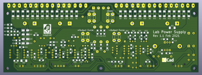
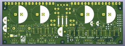
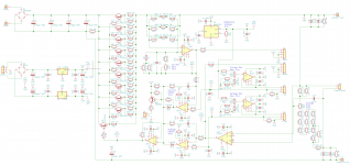
So here's the Rev 1.1 board.
Changes include:
Board size is unchanged.
Changes include:
- Fixing the current feedback network stuff-up.
- Improvements to the voltage feedback divider to make it less susceptible to resistor TC.
- Buffering current and voltage set potentiometer outputs so that changes in pot resistance won't affect anything.
- Beefing up the tie-points between voltage output and sense (using RS1B 1A diodes rather than 1n4148, plus adding a 1W 10Ω resistor to each.
- Adding a bleed resistor across the input caps.
Board size is unchanged.
Attachments
A few measurements of the Rev 1.0 board, now that I've stuck it on a heatsink.
First is transient response, with the transient applied to the voltage set input. I used my 3325B with a 1µF cap in series to apply the stimulus. The supply was set to 8V at 1A (running into my 8Ω load), then the squarewave was coupled in from there. The negative-going slope is simply set by the output capacitance and load resistance, as there's nothing to actively pull the output down.
I also did some noise plots, again running 8V at 1A into my 8Ω load. I took snapshots at DC-1MHz, DC-100KHz, DC-10KHz, and DC-1KHz. I think the stuff in the DC-1MHz plot is radio stations. 50Hz is pretty obvious in the DC-1KHz plot. It's reasonably quiet - the 50Hz component is 105µV.
That's the good. The bad is that the load regulation is pretty awful. A 1A change in output (unplugging the load) is accompanied by tens of millivolts variation. It really shouldn't do that. Careful poking and prodding shows what's happening here. By taking the reference ground from the output +ve rather than the +sense node, any difference between output +ve and sense +ve is just added to the feedback voltage.
The quick fix is to simply swap the gnd node to sense +ve, but I think a more robust method is to use an instrumentation amp to sense the voltage across the voltage sense resistor. So on to Rev 1.2!
Attachments
-
 Lab supply transient response.gif6.1 KB · Views: 115
 -
 Lab Supply Noise DC to 1KHz 8V 1A out CV mode.gif18.4 KB · Views: 95
 -
 Lab Supply Noise DC to 10KHz 8V 1A out CV mode.gif20.1 KB · Views: 81
 -
 Lab Supply Noise DC to 100KHz 8V 1A out CV mode.gif17.8 KB · Views: 97
 -
 Lab Supply Noise DC to 1MHz 8V 1A out CV mode.gif17.1 KB · Views: 133
 -
 Screen Shot 2021-02-28 at 3.24.49 pm.png382.2 KB · Views: 164
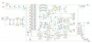
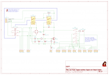
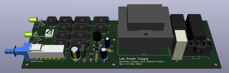
Knocked out a second board to do the 12VAC center tapped supply to drive the main regulator board circuitry, plus do a soft-start for the main 300-500VA transformer, plus do an "output enable".
The output enable is based on a big 4PDT latching pushbutton switch - an ALPS SPUN part. When the output is not enabled (button out) the two meters on the front are connected to the pots, making setting current straightforward (no need to short the output), and the voltage set to the regulator board is hooked to 0V, effectively making the regulator board output 0V.
I've seen other designs that use a relay to disconnect the output, but it's a whole lotta current so would need a very big relay. I figure the pass transistors should do a reasonable job here.
So when we press the output enable button, the pots are connected up to their respective regulator board inputs, and the displays are connected to the regulator board monitor outputs.
The soft start is a straightforward design based on a power amp I did years ago. I use a second relay for switching mains to the big transformer as well, this way I can do my power switch (another ALPS SPUN part on another board - yet to be designed), at 12V rather than 240.
The board is 180mm x 60mm. I've put all the lethal mains stuff in one corner, and made provision to attach a shield (another piece of PCB) to the back of the board so fingers can't get to mains potential stuff. I've used a Molex Mega-Fit connector for both main power transformer and power inlet rather than 0.25" spades, that way there's no exposed metal on the component side.
Attachments
Last edited:
The Rev 1.2 board is all together, and it really does work nicely.
I can set the output up to 10.0000V (measured with my HP3478A) into my 8Ω load, wander away and make a cuppa, then come back to a lovely hot heatsink and a meter reading of 10.0005V. Not bad.
A small 200mA load step (adding a 50Ω load across the 8Ω load) makes the voltage change from 10.0000V to 10.0007V. This is more due to the placement of my sense wires than anything else.
I'm using a 1K 5 turn pot for coarse set in parallel with a 50K 5 turn pot for fine set. That combination is good for 0.1mV setability (ie the resolution of my 3478A).
I reckon that'll do. Now to get to work on building and writing the code for the meters.
Last edited:
I think it should be pretty good. If you short the output it just goes constant current. If you connect the output to a higher voltage than the supply is set for it just doesn’t source current. The sense inputs are tied to their respective outputs by 10Ω resistors and back to back diodes, so they should be moderately difficult to damage...
I’m not terribly creative in finding ways to damage things.
I’m not terribly creative in finding ways to damage things.
I think, I found a possible solution for the transformer, Antek AS-4445: AS-4445 - 400VA 45V Transformer - AnTek Products Corp
Only $51 USD.
Antek AS-4445 Electrical Characteristics, Outputs 4x, Power = 400VA
Output V .......Current
45V ........ ........ 4.4A
45V ........ ........ 4.4A
15V ........ ........ 2A
15V ........ ........ 2A
Only $51 USD.
Antek AS-4445 Electrical Characteristics, Outputs 4x, Power = 400VA
Output V .......Current
45V ........ ........ 4.4A
45V ........ ........ 4.4A
15V ........ ........ 2A
15V ........ ........ 2A
The transformer I’ve been using is an old Jaycar 2x25V, 300VA toroidal, with the secondaries in parallel. It’s only good for ~40VDC, but will do for now. A suitable one would be: RS PRO 2 x 115V ac, 2 x 45V ac Toroidal Transformer, 500VA 2 Output | RS Components or https://www.altronics.com.au/p/m5545-powertran-45-45-300va-toroidal-transformer/
But really, anything in the 25VAC to 45VAC range at >300VA. The max current and voltage will be affected depending. It’s hard to spec something specific as it will depend on what’s available locally. Transformers are expensive to ship.
But really, anything in the 25VAC to 45VAC range at >300VA. The max current and voltage will be affected depending. It’s hard to spec something specific as it will depend on what’s available locally. Transformers are expensive to ship.
Last edited:
Thank you. Yes, shipping is the main issue for transformers & heat sinks. I really miss the local surplus electronics shops.
The packaging cost (chassis) and shipping cost is the major driver of low cost switched mode power supplies versus expensive linear supplies, these days.
The packaging cost (chassis) and shipping cost is the major driver of low cost switched mode power supplies versus expensive linear supplies, these days.
The Rev 1.2 board is all together, and it really does work nicely.
I can set the output up to 10.0000V (measured with my HP3478A) into my 8Ω load, wander away and make a cuppa, then come back to a lovely hot heatsink and a meter reading of 10.0005V. Not bad.
A small 200mA load step (adding a 50Ω load across the 8Ω load) makes the voltage change from 10.0000V to 10.0007V. This is more due to the placement of my sense wires than anything else.
I'm using a 1K 5 turn pot for coarse set in parallel with a 50K 5 turn pot for fine set. That combination is good for 0.1mV setability (ie the resolution of my 3478A).
I reckon that'll do. Now to get to work on building and writing the code for the meters.
Suzy,
Did you have a schematic for the final version of this? I've been meaning to get something along these lines together for a long time but just haven't had the time.
Nice - four terminal too. Only thing I would probably add is a 10A IEC filter on the mains side and a MOV.
I was thinking that the board could have a slot to reduce heat conduction through the PCB?
Lastly - and this is a beginner question - would you use something like a bridge (wheatstone/kelvin/fontana) to compensate for the lead parasitic impedance?
EDIT: sorry I mean kelvin not Johnson
I was thinking that the board could have a slot to reduce heat conduction through the PCB?
Lastly - and this is a beginner question - would you use something like a bridge (wheatstone/kelvin/fontana) to compensate for the lead parasitic impedance?
EDIT: sorry I mean kelvin not Johnson
Last edited:
- Home
- Design & Build
- Equipment & Tools
- Lab supply using Lateral MOSFETs