 This thread has been split from here - Autoranger for soundcards - at request.
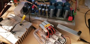
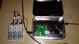
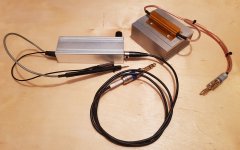
 Hi! My setup for measuring Power Amplifier THD 1. Load (4 Vishay Metal Film resistors) 2. Generator with battery 3. Relay attenuator with 1dB step 4. SC Asus Xonar Essense STX II
Dropbox - 20200828_002917.mp4 - Simplify your life
Attachments
Last edited by a moderator:
Hi! My setup for measuring Power Amplifier THD 1. Load (4 Vishay Metal Film resistors) 2. Generator with battery 3. Relay attenuator with 1dB step 4. SC Asus Xonar Essense STX II
Dropbox - 20200828_002917.mp4 - Simplify your life
Side note, those 10ohm metal film resistor in TO220 (Vishay or whatever) are making quite a poor load... Metal film resistors, even the "power" ones, have very limited current and dI/dt capabilities. That is, they won't survive any high current pulse and can easily be destroyed by a transient at full power. They make pretty efficient fuses, which could be sometimes viewed, in certain applications, as a feature, but not as high power loads in audio. Really, for audio, there's no good substitute for wire wound resistors, ideally anti-inductive.
Correct- the film and related won't survive. I have the smoking ruins to prove it.
The Caddock and Vishay resistors just turn into fuses. The cheap ($2) china wirewound resistors 50W/100W 0.01-50 Ohm Shell Power Aluminum Housed Case Wirewound Resistor New | eBay measure very resistive to 100KHz, better than 2' of zip cord. And you have a heat sink already. Keep the wiring close as pairs as much as possible. The large "windows" will be the dominant inductance in your jig.
The Caddock and Vishay resistors just turn into fuses. The cheap ($2) china wirewound resistors 50W/100W 0.01-50 Ohm Shell Power Aluminum Housed Case Wirewound Resistor New | eBay measure very resistive to 100KHz, better than 2' of zip cord. And you have a heat sink already. Keep the wiring close as pairs as much as possible. The large "windows" will be the dominant inductance in your jig.
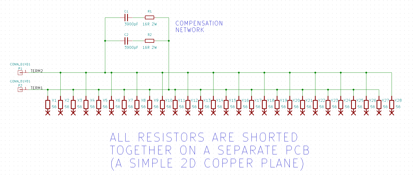
You can remove a lot of inductance using a simple compensator
Building my own noninductive 8R 150W load using wire wound resistors
_
Building my own noninductive 8R 150W load using wire wound resistors
_
The cheap ($2) china wirewound resistors 50W/100W 0.01-50 Ohm Shell Power Aluminum Housed Case Wirewound Resistor New | eBay
This is the first time I have applied such a load. I won't explain why, but it won't do at all
what is the software suite you are using?
SpectraPLUS-SC - Features and Specifications
Attachments
Last edited:
Given the "Auto" part of the AutoRanger with the corresponding inevitable overrange, this discussion is highly applicable to the thread, and thank you all for diving in!
So far I have only used the AutoRanger for line-level testing but I can imagine the difficulty clamping a transient when testing amplifiers without damage to the unit.
Howie
For testing power amplifiers, I usually implement a precision 10:1 voltage divider right at my dummy load. This is reasonable, since power amps have gain that needs to be reduced anyway. A 900-ohm/100-ohm divider with 1% resistors is usually enough protection, and the low impedance of the divider keeps the noise down. The resistors need to have adequate power rating, both for reasons of dissipation and minimization of thermal distortion at low frequencies.
Cheers,
Bob
+1 ?It won't do what?
If it was a comment about TO220 resistors then I think they have too little thermal mass (and surface?) and too high TCR. So TO220 resistors vary their resistance too much for accurate low-distortion measurements.
So I prefer to use large wired resistors. The larger the rated power - the better.
But I have to add that such a way may lead to increased measured distortion because of the presence a copper connecting wire with its own resistance and high TCR (and TCR of a copper is a bit nonlinear too). So this is ok for most amps except ultra-low distortion ones.For testing power amplifiers, I usually implement a precision 10:1 voltage divider right at my dummy load.
For ultra-low distortion measurements, we have to connect the divider (I mostly use 1:10 too, usually 1800R:200R) connected directly to the amp output (output terminals).
Last edited:
The copper won't add distortion in the audio range. Its time constant is too long (or its so thin it is about to burn through). Its resistance may degrade the accuracy of your measurement but not by much if you use reasonable wire. if you need higher accuracy measuring the voltage at the amp terminals makes some sense. A divider right there also makes sense. You could optimize the divider to 50 Ohms out and connect via a 50 Ohm BNC cable. A small trim caps across the divider resistor to compensate would give extended bandwidth way beyond audio.
It is debatable. I can't agree with you. (of cause its time constant is likely too large, but...). For example, let's take an extreme case to measure THD: let's measure THD on the acoustic system input terminals (connected with 3m 16AWG/1.5mm2 cable). You'll find a THD of about 0.01%-0.1% for an 0.001% amp.The copper won't add distortion in the audio range. Its time constant is too long (or its so thin it is about to burn through).
If we'll measure THD on a dummy load with short (<1m) copper wire then THD will still noticeably degrade (not a bit but it may degrade at times).
The reason may be of cause not only wires but their interaction with non-copper load resistance (so it makes a non-linear divider).
I haven't investigated this effect much. I just noticed it and want to share.
I guess this effect may possibly disappear only if we use a dummy load of a much higher (infinite) rated load and too thick (non reasonably too thick) wires.
Last edited:
It is debatable. I can't agree with you. (of cause its time constant is likely too large, but...). For example, let's take an extreme case to measure THD: let's measure THD on the acoustic system input terminals (connected with 3m 16AWG/1.5mm2 cable). You'll find a THD of about 0.01%-0.1% for an 0.001% amp.
If we'll measure THD on a dummy load with short (<1m) copper wire then THD will still noticeably degrade (not a bit but it may degrade at times).
The reason may be of cause not only wires but their interaction with non-copper load resistance (so it makes a non-linear divider).
I haven't investigated this effect much. I just noticed it and want to share.
I guess this effect may possibly disappear only if we use a dummy load of a much higher (infinite) rated load and too thick (non reasonably too thick) wires.
What I think you are seeing is the non-nonlinearity (current distortion) of the load showing in the resistive loss on the wire. When looking at PPM distortion and a load with say .1% nonlinearity (really good speaker) that will show in the current which become voltage across the wire in series with the distortion of the amp. The distortion is real but its source may not be what you think. Replace the speaker with a big wirewound resistor and see what distortion you get. Its also meaningful to put a small resistor in series with the load and look at the current and its distortion.
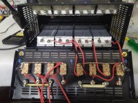
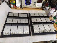
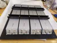
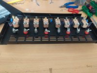
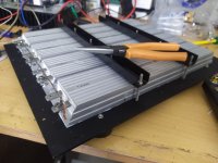
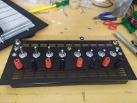
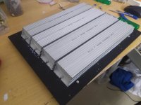
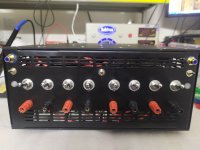
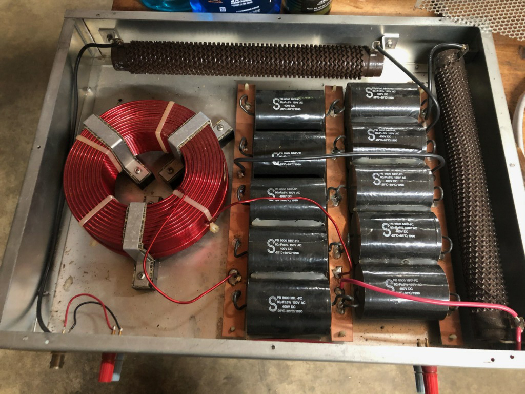
Hi have made a dual channel dummy load for my amp testing , its made from 500W wire wound resistors in an aluminum shell which is in turn connected to 400X300mmX3 mm aluminium sheet. It can be switched for 8ohms , 4ohms , 2.66ohms and 2ohms. I have also kept 10X & 100X attenuation out put to be used with sound cards.
I have tested upto 400W amps for continuously 4 hrs they do get hot but after turning on the 2X120mm - 200CFM fans the heat is manageable.
for 10x & 100X attenuation i Have bought vishay 100K,10K & 1K 1% low TCR resistors
Regards
I have tested upto 400W amps for continuously 4 hrs they do get hot but after turning on the 2X120mm - 200CFM fans the heat is manageable.
for 10x & 100X attenuation i Have bought vishay 100K,10K & 1K 1% low TCR resistors
Regards
Attachments
-
 IMG_20210308_001814.jpg575.2 KB · Views: 284
 -
 IMG_20210307_141453.jpg469.9 KB · Views: 257
 -
 IMG_20210307_141334.jpg364.7 KB · Views: 480
 -
 IMG_20210307_011803.jpg291.8 KB · Views: 454
 -
 IMG_20210307_011712.jpg465.1 KB · Views: 466
 -
 IMG_20210307_011700.jpg321.7 KB · Views: 469
 -
 IMG_20210306_213959.jpg503.3 KB · Views: 492
 -
 IMG_20210308_005902.jpg303.3 KB · Views: 301

What I think you are seeing is the non-nonlinearity (current distortion) of the load showing in the resistive loss on the wire. When looking at PPM distortion and a load with say .1% nonlinearity (really good speaker) that will show in the current which become voltage across the wire in series with the distortion of the amp. The distortion is real but its source may not be what you think. Replace the speaker with a big wirewound resistor and see what distortion you get. Its also meaningful to put a small resistor in series with the load and look at the current and its distortion.
Any thoughts regarding the use of the IHF model reactive dummy load as opposed to just resistors? We constructed four 8 ohm IHF loads, each one built to take 400 W:
When testing amplifiers for various usages we found several which tested well and seemed stable into non-inductive resistors which misbehaved, some so much they gave up the magic smoke into the IHF load.
It seems somewhat off the mark to be stressing over miniscule copper thermal effects when the actual reactive speaker loads will have much different VI characteristics than a resistor, and in theory at least, the IHF load shows more accurately how an amp will behave into a speaker-like load.
The EPDR which REW displays may show correlation to this behavior, it will be interesting to find out!
I'm interested in knowing what people feel about this...
Cheers!
Howie
Howard- The IHF load is a nice conceit but if you want to make sure your amp is stable you need more than a single load solution. Caps and R/C networks are better for finding stability issues. The IHF load will help find inadequate heat sinks or SOA but drive a 2 uF cap with a .1 Ohm resistor and you will find the amps limits pretty quick it needs to be a pretty good high current cap. And caps in steps between .01uF and 1uF almost always will get some instability. You may need a square wave or an impulse to get it started.
1Audio said:
"Howard- The IHF load is a nice conceit but if you want to make sure your amp is stable you need more than a single load solution. Caps and R/C networks are better for finding stability issues. The IHF load will help find inadequate heat sinks or SOA but drive a 2 uF cap with a .1 Ohm resistor and you will find the amps limits pretty quick it needs to be a pretty good high current cap. And caps in steps between .01uF and 1uF almost always will get some instability. You may need a square wave or an impulse to get it started."
Understood, it is obvious that different speakers pose very different reactive loadings. We settled on the standard IHF load precisely because we could exchange data with manufacturers, in our case Crest, QSC and Crown who also had IHF loads.
Also agreed about instability into capacitive loads, although it may be controversial we often isolated the amp's output with 0.1-0.22 ohms which greatly reduced ringing / instability without affecting response more than a simple eq touch up could correct for.
I guess my initial point is we derived very little useful data using resistive dummy loads...from a system design POV. From an amp designers POV like yours it is likely different.
The IHF load has new relevance for me with the relatively recent inclusion of EPDR into REW. Some speakers I can have shipped here for testing, but not most. Studio speakers tend to be large, heavy, and expensive and I don't have room in my lab to fit many of them. Also some manufacturers my customers want to use do not want to send samples for testing.
To be able to do a relatively meaningful amp test here potentially cuts out expensive/time consuming/days of travel to test the speakers with the amps themselves. I have configured an RME ADI-2 Pro/laptop with REW and a small impedance test box which can be sent with one of our field tech to test speakers in situ, then email me the sweeps. By keeping a folder of these different studio speaker impedance and EPDR sweeps obtained remotely, I can test amps here against the IHF load and compare their stability and limiting characteristics into the IHF load. I would love to create a suite of reactive loads which precisely model the speakers I need to specify, but this idea is a second best. I gave a bit of thought to reconfiguring these IHF loads to be switchable for various characteristics, but that would be quite difficult.
Sure, this does not fully characterize the amp/speaker match, but for studio purposes it should serve better than testing amps with a resistor which approximates the speaker mfgr's "nominal impedance" rating...which itself does not give minimum impedance/frequency data.
Everything is a compromise...but some compromises are better than others!
Cheers!
Howie
Being able to exchange info with your vendors is important. If you call and say the amps belch smoke with these speakers they will say stupid you for using those useless speakers. however if you say they belch smoke on the IHF load at 20W then a real conversation can be had.
I deal with similar on headphones. There is an IEC sensitivity standard and you need all the specific pieces (IEC couplers, mikes, specific eq's etc. to check for it. But those are not useful for day to day work because they are too unique to the international standards cabal. For day to day work its simple flat plate couples and ecm mikes. $200 max vs $8000 entry.
I deal with similar on headphones. There is an IEC sensitivity standard and you need all the specific pieces (IEC couplers, mikes, specific eq's etc. to check for it. But those are not useful for day to day work because they are too unique to the international standards cabal. For day to day work its simple flat plate couples and ecm mikes. $200 max vs $8000 entry.
- Home
- Design & Build
- Equipment & Tools
- Dummy Load