Full duplex up to 192kHz/24bit, but usable only at 48kHz with ARTA, REW and the alike.
Why can't it be used up to 192 kHz?
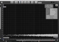
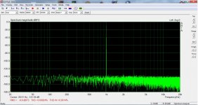
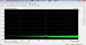
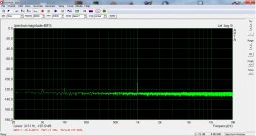
In the first 3 photos, I see only 100 Hz and its harmonics. No 50 Hz is present.
To my opinion this is due to noise from the power supply lines or noise from the grounding of the circuit.
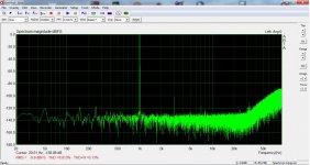
In the other 2 photos, I see 50 Hz and 100 Hz.
But the 50 Hz and its harmonics are much bigger.
To my opinion this means that the circuit picks-up noise from the mains. Try to find why by using a lower value potentiometer (10 k ?) or to remove the bulbs or to shield better.
I hope it's not the power lines after the regulators. Besides, everything is running on symmetrical psu except the CS4272. I can't tell if the ground planes are responsible for the 100Hz noise but it seems that it is of very low magnitude anyway. Moving or shielding the transformers doesn't help. Keeping it silent at very high input impedance is definitely a challenge. I'm relying on CMRR. For this, the light bulbs should placed at least on the same level side by side I think. Or completely substituted for something else. I'll try this.
Why can't it be used up to 192 kHz?
It gets unstable at any sampling rate higher than 48kHz. I had this issue with my Behringer UMC202 too. Perhaps something wrong with my PC?
+1. There is a need to decrease a 100 Hz harmonics from power supplies (I can't say an exact line). It can be easily found out with a large cap in parallel to existing power supply filters. And possibly some 100 Hz harmonics go from too thin ground wires somewhere...In the first 3 photos, I see only 100 Hz and its harmonics. No 50 Hz is present.
To my opinion this is due to noise from the power supply lines
Several parallel electrolytic caps in power supply filters like to have a resistor between them to make a CRC-filter, but not a simple C-filter.
And with 12VAC secondaries, we may use 1000 uF 25V rated caps instead of 470 uF 35 V rated. A CRC-filter with even low (1-5 R) resistors has to help a lot. And consider placing RC snubbers across secondaries (0.1...0.47uF, 10R).
Last edited:
Have you tried another USB-cable?It gets unstable at any sampling rate higher than 48kHz. I had this issue with my Behringer UMC202 too. Perhaps something wrong with my PC?
It gets unstable at any sampling rate higher than 48kHz. I had this issue with my Behringer UMC202 too. Perhaps something wrong with my PC?
Any problem with USB highspeed (480Mbps)?
Thanks!
I think the spikes are PSU related, not having to do with light bulbs. Regard input driver, seems you lose ~5dB vs fosusrite solo witch use the same codec CS4272, but the distortion are really impressive at 0.1dBFS.
Many thanks! Please see attachments. Am I right being suspicious about the light bulbs?
I think the spikes are PSU related, not having to do with light bulbs. Regard input driver, seems you lose ~5dB vs fosusrite solo witch use the same codec CS4272, but the distortion are really impressive at 0.1dBFS.
Attachments
Strange things are happening! Returning to this now it seems to work!!! Still, practically it stops ~30kHz. With REW it doesn't even allow to extend the window beyond 30kHz.
I don't know how to check that...
Correct!
Any problem with USB highspeed (480Mbps)?
I don't know how to check that...
I am just surprised the bulbs allow such tiny distortion.
I assume the measurement is a DAC - ADC loopback, right?
Correct!
Attachments
Have you tried another USB-cable?
Yes! It makes no difference though...
+1. There is a need to decrease a 100 Hz harmonics from power supplies (I can't say an exact line). It can be easily found out with a large cap in parallel to existing power supply filters. And possibly some 100 Hz harmonics go from too thin ground wires somewhere...
Several parallel electrolytic caps in power supply filters like to have a resistor between them to make a CRC-filter, but not a simple C-filter.
And with 12VAC secondaries, we may use 1000 uF 25V rated caps instead of 470 uF 35 V rated. A CRC-filter with even low (1-5 R) resistors has to help a lot. And consider placing RC snubbers across secondaries (0.1...0.47uF, 10R).
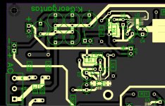
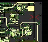
I attached screenshots of the pcb layout. There are ground planes on all three decks connected only via the central metal hex spacer. The pin headers are not connected to gnd. Transformer's CT goes to the cap bank with a dedicated line. Of all six caps, only the last one -here C26 for the neg line- is connected to gnd. Then it splits to the regs via 1Ω. LT3042/94 with 10μF input and output caps. Of course, the layout of the regs is what I thought it works... To my eyes, the problem is shown at the second screenshot. A raw DC line with strong 100Hz shouldn't be harmful by itself but it crosses two of the light bulbs -only one per channel- that is mounted at the bottom of the next deck.
Also attached a earlier measurement taken with the opa1632 connected directly to the attenuator without the bulbs in place.
Attachments
Full duplex up to 192kHz/24bit, but usable only at 48kHz with ARTA, REW and the alike.
Excuse my ignorance but why is it usable only up to 48kHz?
This spectrum looks fine. Possibly bulbs change something?Also attached a earlier measurement taken with the opa1632 connected directly to the attenuator without the bulbs in place.
I think I found it... First, it's not the lamps! Against the odds, they are doing remarkably well! And apparently, it's not EMI at all. Everything is packed between ground planes and this pays off. The problem seems to be the high value potentiometer. 100k may be too much even for fet input op amps. We may get away with the 1/f of opa1656 but there must be something else. I was looking at some loop measurements of my UMC202 and Pete Millett's interface. First pic is the sound card alone and the second is with the interface. So, should anyone needs the 100k input impedance, the best THD+N is what posted earlier. But for better figures, it may have to drop down to 10k. I need to order new parts -and wait for them to arrive- to verify this. Anyway, keep in mind that the true input impedance should be the double for balanced mode which can be used for SE DUTs as well. Only output should be set to unbal to drive a SE DUT.
More work to be done...
I need to order new parts -and wait for them to arrive- to verify this. Anyway, keep in mind that the true input impedance should be the double for balanced mode which can be used for SE DUTs as well. Only output should be set to unbal to drive a SE DUT. More work to be done...
Attachments
About bandwidth
I found a plausible explanation on the internet. The usb speed - theoretically 480 Mbit/s but usually much lower in real life- is shared between multiple channels processed by the microcontroller. And my usb interface runs 8 channels regardless how many are used. It's a matter of firmware. I now can see that it could be ordered for higher sampling rates and 4 channels, but I can't tell if that would made a difference.
I found a plausible explanation on the internet. The usb speed - theoretically 480 Mbit/s but usually much lower in real life- is shared between multiple channels processed by the microcontroller. And my usb interface runs 8 channels regardless how many are used. It's a matter of firmware. I now can see that it could be ordered for higher sampling rates and 4 channels, but I can't tell if that would made a difference.
Isochronous transfer in highspeed reserves 1024 bytes in every frame. If the DAC requests data every microframe (bInterval = 1) that makes 1024 x 8000 = 8,192,000 bytes per second. IIUC you are using something like XMOS Multichannel high-quality USB to/from I2S/DSD SPDIF PCB - DIYINHK which runs at 192/8/24or32.
The vendor speficies 8ch@192kHz which even for 32bit sample size is within a single isochronous packet (1024 bytes max) per microframe (125us).
I have asked before - are you sure your link runs at USB highspeed 480Mbps? Because the limits you get are typical for fullspeed 12Mbps.
I have asked before - are you sure your link runs at USB highspeed 480Mbps? Because the limits you get are typical for fullspeed 12Mbps.
- Home
- Design & Build
- Equipment & Tools
- DIY soundcard intended for measuring amplifiers