Kostas the pleasure is mine.
A very good software (REW) can make a dumb monkey look like a smart monkey if only he finds the right buttons to push.
But a very good software can't polish a turd.
Besides having built yourself a very good piece of test instrument, you have demistified the black box that a soundcard is (was) to some of us.
George

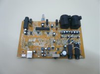
The question is plausible, and if If I understand correctly, @jp8 is going that way. ") Myself, I was really trying to find my way with all this back then and I was worrying about too many thin wires poking here and there. Actually, the audio codec chip was easy to include on my PCB. The big problem was the usb interface. Moreover, since I'm completely illiterate in code writing. First attempt was to transfer all parts from the Behringer to a new PCB hopping that the drivers would come together. See attachment. A total failure... It reminds me to stay away from BGA chips. So, next step was a DIYINHK module and manual control.
Myself, I was really trying to find my way with all this back then and I was worrying about too many thin wires poking here and there. Actually, the audio codec chip was easy to include on my PCB. The big problem was the usb interface. Moreover, since I'm completely illiterate in code writing. First attempt was to transfer all parts from the Behringer to a new PCB hopping that the drivers would come together. See attachment. A total failure... It reminds me to stay away from BGA chips. So, next step was a DIYINHK module and manual control.

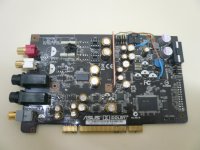
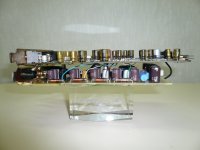
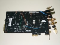
Third picture is an Asus essence STXII with power rails per section separated with a sharp cutter and connected to external regulators made to fit as a double slot PCI card. This project took another route leading to my DAC.
Myself, I was really trying to find my way with all this back then and I was worrying about too many thin wires poking here and there. Actually, the audio codec chip was easy to include on my PCB. The big problem was the usb interface. Moreover, since I'm completely illiterate in code writing. First attempt was to transfer all parts from the Behringer to a new PCB hopping that the drivers would come together. See attachment. A total failure... It reminds me to stay away from BGA chips. So, next step was a DIYINHK module and manual control.Third picture is an Asus essence STXII with power rails per section separated with a sharp cutter
and connected to external regulators made to fit as a double slot PCI card. This project took another route leading to my DAC.Attachments
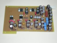
The BGA is the Xmos micro processor extracted from the Behringer soundcard together with all its peripherals. I struggled to reverse engineer the PCB to no avail and I had to follow the application notes of that chip. Either it was somewhere there I messed up or I wasn't lucky soldering the chip itself. It never came to life.
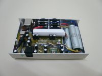
Regarding the other soundcard, if I understand correctly your question, the regulators' PCB is connected with wires to the Asus PCB as shown in post#102. It was a useful expirement about the effect of separate psu for each chip/block of the soundcard. This concept is applied to both my diy soundcard and my DAC.
Regarding the other soundcard, if I understand correctly your question, the regulators' PCB is connected with wires to the Asus PCB as shown in post#102. It was a useful expirement about the effect of separate psu for each chip/block of the soundcard. This concept is applied to both my diy soundcard and my DAC.
Dealing with BGAs takes a lot of courage. At least you tried. I wouldn't have tried that.Either it was somewhere there I messed up or I wasn't lucky soldering the chip itself. It never came to life.
Yes, that is what I meant. Transfer of the concept to your soundcard.It was a useful expirement about the effect of separate psu for each chip/block of the soundcard. This concept is applied to both my diy soundcard and my DAC.
The very clean noise floor is most probably due to these filtered multi PSUs.
The low THD at 0dBFS must be due to increased PSU voltage to the opamps (headroom).
These are the two technical strengths of your soundcard.
The third strong point is it's versatility.
Now the DAC must be another marvel of yours to test
George
- Home
- Design & Build
- Equipment & Tools
- DIY soundcard intended for measuring amplifiers