Wow!! Then effectively it is pulsed DC. I’m having trouble getting my head around that from a practical sense. As an input to an amp for example with a cap filtering DC, pulsed DC is the waveform the circuitry would be seeing. Seems that would throw a monkey wrench into troubleshooting the amp’s circuitry, especially when working with speakers and crossovers. DC coupling on the scope shows pulsed DC waveform. AC coupling ignores the DC bias and shows a plus and minus square wave. Anyway....
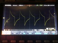
Attached is a picture of the “square wave” that appears at lower frequencies. Above 50-100 hz the top and bottom flatten out. Maybe it sheds some light on the stability issue.
Last night I let it run for several hours and the sine side bouncing remained and the frequency also became unstable. I did notice that touching the square outputs changed things, so I am beginning to see the value in installing a switch to disable the square side when not in use. The rest of your suggestions will be implemented today.
I have seen several references to rewiring the grounds but haven’t seen a detailed description of exactly what is recommended. Any thoughts?
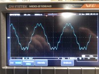
Adding the wave seen on all three Q10 leads. Pay no attention to the frequency readout. I could not get this wave to sync. I had to stop the trigger so I coukd snap the picture. The main wave is 60hz.
Thanks,
Jeff
Attached is a picture of the “square wave” that appears at lower frequencies. Above 50-100 hz the top and bottom flatten out. Maybe it sheds some light on the stability issue.
Last night I let it run for several hours and the sine side bouncing remained and the frequency also became unstable. I did notice that touching the square outputs changed things, so I am beginning to see the value in installing a switch to disable the square side when not in use. The rest of your suggestions will be implemented today.
I have seen several references to rewiring the grounds but haven’t seen a detailed description of exactly what is recommended. Any thoughts?
Adding the wave seen on all three Q10 leads. Pay no attention to the frequency readout. I could not get this wave to sync. I had to stop the trigger so I coukd snap the picture. The main wave is 60hz.
Thanks,
Jeff
Attachments
Last edited:
Voltage readings
I include only Q1-5 as Q6,7&8 are all nominally correct.
TP1 44.5
Bias wiper 25.0
FB wiper 25.1
Qs are B/C/E
Q1 25.8/44.5/25.4
Q2 26.0/43.1/25.4
Q3 43.2/43.9/43.8
Q4 43.9/44.5/43.0
Q5 42.5/0/43.0
Clearly things are not yet right. Caps across rail and C5 had no effect. Turning symmetry down to disable square wave did seem to help a bit.
Thinking of replacing D1, 2 and 8 for the heck of it. I have 1N4007s and 1N4148s on hand. Any idea if the 4007s can replace the 4002 called for on D1 and 2 and the 4148 replace the 4149 called for on D8?
Jeff
Q1
The square wave photo you posted looks largely as expected. No point in replacing D8. If you use DC coupling instead of AC coupling to capture the 10 Hz square wave it should look more square. Disabling the square wave generator is a good idea so you can concentrate on the main oscillator section.
I don't think there's anything to be gained by changing diodes--- I'd leave them alone.
The hum waveform on the collector of Q10 is probably OK; scrutinize base and emitter with ac coupling. We're trying to confirm there's no high frequency oscillation. Be sure to use your scope's ground clip for best waveform fidelity/lowest hum.
Is the generator no longer generating a sine wave? Base and emitter voltages of Q4 and Q5 can't be as reported if the sine wave circuit is working.
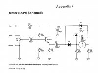
You mentioned in an earlier post that you'd added an enhancement of the meter circuit. Can you provide details and perhaps a schematic?
I've no opinion of Heath's prescribed grounding other than I'd defer working on it until all else is working properly. But while on this subject, the ideal way to look at residual is to turn the Feedback control to minimum; sine wave will stop and TP H should bias to about mid supply (~ 22V dc). Any hum (cover in place) at the output is an imperfection.
Best,
Steve
The hum waveform on the collector of Q10 is probably OK; scrutinize base and emitter with ac coupling. We're trying to confirm there's no high frequency oscillation. Be sure to use your scope's ground clip for best waveform fidelity/lowest hum.
Is the generator no longer generating a sine wave? Base and emitter voltages of Q4 and Q5 can't be as reported if the sine wave circuit is working.
You mentioned in an earlier post that you'd added an enhancement of the meter circuit. Can you provide details and perhaps a schematic?
I've no opinion of Heath's prescribed grounding other than I'd defer working on it until all else is working properly. But while on this subject, the ideal way to look at residual is to turn the Feedback control to minimum; sine wave will stop and TP H should bias to about mid supply (~ 22V dc). Any hum (cover in place) at the output is an imperfection.
Best,
Steve
Last edited:
I tested voltages per the instructions on Page 71, with all controls and PCB pots full CCW, therefore no generating. When feedback and bias are rest waves return.
It has been running for several hours straight today more stable than usual. But occasionally with no touching, adjusting or probing and the amplitude begins to bounce and sometimes the frequency goes erratic as well. Then just as suddenly it will stabilize. When I can catch it bouncing and can get a second scope probe on the Qs, the voltages are all bouncing in sync with the wave.
The meter buffer board comes from the new Heathkit owners. The website is Data Professionals Main Page. It comes with the “Heathkit IG-18 THD Modification Kit”. Shematic attached. The kit consists of the meter buffer board and instructions for modifying the Variable Frequency Units control and upgrading caps and resistors, although in the case of later IG-5218s like mine only the caps needed to be upgraded as all other mods had already been incorporated by the factory. The only other mod I made was replacing the incandescent power lamp with an LED, and that just yesterday.
It has been very well behaved the past hour. I can make it bounce by tapping the case, and it takes 5-10 seconds to settle down. But those voltages are off on Q1-5. Hope this info is useful. Thanks.
Attachments
I have an IG18 that I have finished repairing and restoring, if you would like photos or measurement, by all means just ask.
Thanks.
Voltage readings
Qs are B/C/E
Q4 43.9/44.5/43.0
Q5 42.5/0/43.0
The output section Q4 Q5 is a push-pull emitter follower and the bases MUST bias around half supply (the output will follow).
Instead they are jammed high.
Open R12 might do that but Q4 Q5 bases would be even closer together.
My hunch is that Q1 or Q2 is blown open. That should not happen, but much in this unit "shouldn't be". Q1 Q2 may be replaced with jellybean NPN: BC547B 2N3904 etc. If that pulls the whole amp so the output is centered, then Q1 Q2 were indeed bad. We may ask if Q1 Q2 should really be super-good. My recollection is that Heath really did design it for modest-spec parts. The 4700 between bases spoils any high hFE part.
There's been much new thinking on opamp design but in a *lamp-bridge* some nonlinearity is essential for stability.
Hi Jeff
I don't have a page 71 in my docs; could you send me a link or PDF so that we're looking at the same sheet of music?
Your meter buffer upgrade looks perfectly reasonable.
Susceptibility to tapping might indicate a flakey connection or simply an intermittent connection in a rotary switch. Cleaning contacts might help if you haven't done so.
You might try gentle, localized tapping with a pencil or similar insulated tool to spot a suspect joint or component.
But if there's consistent misbehavior at higher operating frequencies, it would seem that there's some defect yet to be found other than just ordinary intermittency. Perhaps tackling a reliably present problem might be a more fruitful attack. But I don't have a formulated plan to suggest. There could also be more than one problem in play.
Do you have other test equipment available for more elaborate trouble-shooting?
I have tapped, tugged and wiggled just about every component with no significant response. I have also cleaned all switches and tested continuity. I have an LCR with Kelvin leads that can usually test in situ. When a questionable value was shown I removed the component and tested again. Any that were out of tolerance (only one) was replaced.
I have the GW MDO-2102AG with its own builtin AWG, a Fluke 77 DVM and a B&K DC power supply. A Heathkit TT-1A is the next restoration project.
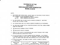
PRR may be on to something. I have attached the instruction page for the voltage measurements which effectively shut the generator off as shown in steps 4 and 8. Would it be any help to test the voltages while the unit is generating?
I have the GW MDO-2102AG with its own builtin AWG, a Fluke 77 DVM and a B&K DC power supply. A Heathkit TT-1A is the next restoration project.
PRR may be on to something. I have attached the instruction page for the voltage measurements which effectively shut the generator off as shown in steps 4 and 8. Would it be any help to test the voltages while the unit is generating?
Attachments
The output section Q4 Q5 is a push-pull emitter follower and the bases MUST bias around half supply (the output will follow).
Instead they are jammed high.
Open R12 might do that but Q4 Q5 bases would be even closer together.
My hunch is that Q1 or Q2 is blown open. That should not happen, but much in this unit "shouldn't be". Q1 Q2 may be replaced with jellybean NPN: BC547B 2N3904 etc. If that pulls the whole amp so the output is centered, then Q1 Q2 were indeed bad. We may ask if Q1 Q2 should really be super-good. My recollection is that Heath really did design it for modest-spec parts. The 4700 between bases spoils any high hFE part.
There's been much new thinking on opamp design but in a *lamp-bridge* some nonlinearity is essential for stability.
Thanks. I am tempted to replace Q1 and 2 based on your feedback. Your and Steve’s general circuitry knowledge is vastly superior to mine. Your comment about the 4700 ohm resistor tells me you may be working from an IG-18 standpoint. I should point out that Heathkit changed R3 to 56K on the IG-5218. Does that change your recommendation on replacement part numbers for Q1 and 2?
Jeff, your testing has been very thorough. Kudos!
I hadn't discovered PRR's post when I was creating my own post but I concur completely with his analysis. However, your post indicated the oscillator was working. I can't reconcile a functioning oscillator with the bias voltages you noted. The voltages Heath notes on its schematic are what I would expect with a properly trimmed and operating circuit and NOT what I'd expect with with PCB pots (ie R7 & R9) set full CCW as instructed in Note 8 of the Heath attachment.
Yes, I would advocate noting voltages while unit is operating. I also suggest the test I mentioned above as a sanity check (my own ): set Feedback pot wiper to the C5 end (this is CCW?) and look at TP H. It should be about 21V with no oscillation present.
I hadn't discovered PRR's post when I was creating my own post but I concur completely with his analysis. However, your post indicated the oscillator was working. I can't reconcile a functioning oscillator with the bias voltages you noted. The voltages Heath notes on its schematic are what I would expect with a properly trimmed and operating circuit and NOT what I'd expect with with PCB pots (ie R7 & R9) set full CCW as instructed in Note 8 of the Heath attachment.
Yes, I would advocate noting voltages while unit is operating. I also suggest the test I mentioned above as a sanity check (my own
): set Feedback pot wiper to the C5 end (this is CCW?) and look at TP H. It should be about 21V with no oscillation present.> test the voltages while the unit is generating?
I would think: "both?"
No-signal, it has to come to a happy DC point or it won't do signal well. With signal, DC points may change, but in the sine side of this box "not much". The open-loop distortion is under 10%, so the DC shift could be 5% (20V to 21V), and probably much less until driven into gross clipping.
4700, 56k, I remember both values and I'm not sure why. The Ideal oscillator does not need it (DC passes through the filter?). Compare to H-P 200AB (tubes, Wien). One built of BJTs may need more base current. The cross-base connection has very little influence on closed-loop signal gain. Yet I do remember two values here. I don't think it was a major change. 4700 may have been a hasty-fix for some production variance.
TP H is 23.0vdc with feedback at minimum, therefore no oscillation. No detectable hum.
By the way disregard the scope trace of the square wave that looks like pulses instead of flat top and bottom squares. It is the scope’s inability to deal with very low frequencies.
Couple more datapoints; the most instability occurs at the lowest (.003v) amplitude setting. Clarification on tapping responses. No matter where I tap lightly the amplitude flares momentarily. It SEEMS the flaring is a bit worse when tapping Q10 and the lamp, but it is highly subjective. And lastly, stability improves with time. Very infrequent instability after 4-5 hours of power-on time. VERY unstable for first 10-30 minutes.
Stable oscillation voltages (B/C/E):
Q1 22.0/44.1/21.4
Q2 22.0/43.6/21.4
Q3 43.6/22.7/44.1
Q4 22.7/44.4/22.2
Q5 21.5/0.0/22.0
Thanks! Those voltage readings are very reassuring.
Does behavior at high-end frequencies also stabilize with operating time?
A few more scattershot thoughts, no particular order:
You noted "the most instability occurs at the lowest (.003v) amplitude setting." This is a very curious symptom/clue. That it's most obvious on the 0.003V setting suggests there might be an intermittent resistor in the output attenuator, e.g. R118 or R121. An interesting experiment would be to disconnect either end of R109. This will remove the entire attenuator from the sine source; then you could see if stability improves. (You might also be suspicious of C10 since it's the only connection between circuit and safety grounds and is electrically close to R121).
I can believe the warm lamp might be sensitive to tapping--- its resistance might vary when the filament is flexed by thumping. An interesting experiment would move the lamp off board and outside the box on a twisted-wire pair. Then tapping experiments could be better isolated.
That Q10 might be sensitive reminds me of an audio amp I built from Popular Electronics, circa late '60s. It used transistors resembling Q10 (RCA) and one of them went leaky, presenting as a loud crackling in the speaker. I had a a hell of a time finding it as the culprit. I'm betting my amp and your Heathkit were born in the same era. Perhaps your Q10 could be at fault. If your bench power supply can produce ~40V, you could power the oscillator with it to test if Q10 at fault.
Extending the leaky/noisy transistor notion, you could replace all the oscillator transistors. I detest guesswork-replacement trouble-shooting, but sometimes it's the easiest course.
Good luck!
Steve
Last edited:
Good news. I have read Reg Williamson’s and Dick Moore’s articles on improving the IG-18/5218 and was planning on implementing at least some of their suggestions once I got the stock unit working reasonably well.
Both complained about what they viewed as a fundamental mistake in design. Namely the ground logic. They both endorsed changing the ground points for the sine and square outputs. The sine ground should go to point L (or any of the common ground trace on the PCB) and the square ground that was on point L should go to the transformer center tap ground.
Magic! The output is now rock solid instantly at startup on both sine and square, with the only remaining anomaly being both sine and square output frequency going unstable at output voltages below about 5mv. Above that rock solid from 3hz to 110mhz!
I had already ordered new transistors so when they arrive I’ll be faced with the decision to fix what ain’t broke, but for now I’m pleased. At 5v and up the amplitude is steady +/- 1mv and the frequency so steady I have to keep checking to be sure my scope hasn’t stopped triggering.
I hope this is useful info for anyone else who may be having a similar experience.
Thanks to all for your generous and timely help. Any ideas on the low signal level frequency issue will certainly be welcomed but the generator will be quite useful in its current state.
Not sure how with my limited knowledge but I will be looking for ways to return the favors.
Jeff
That's great news!
Since the frequency is generated by the sine wave oscillator at a constant 10V RMS, I'd wager that the frequency isn't really dropping at low amplitudes. I surmise your using some sort of frequency counter or relying upon your scope trigger to measure frequency. Rather, I suspect that low amplitudes the counter or the trigger circuit is failing recognize every cycle consistently so it appears to drop in frequency. All completely normal.
Again congrats!
- Status
- This old topic is closed. If you want to reopen this topic, contact a moderator using the "Report Post" button.
- Home
- Design & Build
- Equipment & Tools
- IG-5218 Assembly error?