Hey folks!
I've seen several great ABX box projects on here already, but not one which was quite what I was looking for, so I thought I'd make my own, and make the design available as open source.
I thought I'd post the process along the way here in case any good feedback pops up
Goals:
Haven't thought too much about case options, but it will likely be a hammond cast aluminum stop box, or an aluminum extrusion, possibly with PCB endplates.
Non-goals:
Functional description
Relay operation
I have a basic schematic drawn up (attached), and I thought I'd post here before drawing up the PCB, in case anyone has any good suggestions!
I've seen several great ABX box projects on here already, but not one which was quite what I was looking for, so I thought I'd make my own, and make the design available as open source.
I thought I'd post the process along the way here in case any good feedback pops up
Goals:
- Switching headphone-level signals
- Relatively inexpensive
- 3.5mm TRS jack inputs / output
- Simple push-button operation
- LEDs for status indication
- Operate from 9V battery
- Draw power only while a button is pressed (good battery life)
- Latching relays
- PCB design and Arduino firmware published on github (MIT license)
- Gerber files published for public use (order your own PCB's)
- Accessible to everyone: through-hole / easy to solder parts, Arduino Nano as drop-in processor, easy to program via USB.
- KISS!
Haven't thought too much about case options, but it will likely be a hammond cast aluminum stop box, or an aluminum extrusion, possibly with PCB endplates.
Non-goals:
- Switching amp-level / speaker-level signals
- "Money is no object" components / design
Functional description
- Physical inputs X and Y are mapped to conceptual inputs A and B, but this mapping is hidden from the user.
- User interface: 3 buttons (Re-roll, Switch, Reveal) and 4 LED's (X, Y, A, B).
- Each momentary button connects power to the circuit / Arduino. Power is drawn from the battery only while a button is depressed.
- Each button also connects power to a unique Arduino pin which identifies the function to the Arduino (8V_REROLL, 8V_REVEAL, 8V_SWITCH).
- "Re-roll" button: randomly decide a new X/Y to A/B mapping (stored in EEPROM), disconnect the output relay, switch the input and dummy relays several times in a manner which maintains the secrecy of the mapping, reconnect the output relay, illuminate the initial selection ("A") LED (which remains lit until the button is released).
- "Switch" button: switch from input A to input B or vice versa, then illuminate the "A" or "B" LED (which remains lit until the button is released). The switch selection is stored in EEPROM.
- "Reveal" button: A pair of LED's is illuminated which reveals the secret mapping to the user (one of A&X, A&Y, B&X, or B&Y).
Relay operation
- Left, Right and Return signal lines each have two relays in series
- The output relay is disconnected first,
- ...then the input relay is switched,
- ...then the output relay is reconnected.
I have a basic schematic drawn up (attached), and I thought I'd post here before drawing up the PCB, in case anyone has any good suggestions!
Attachments
Last edited:
Example operation:
This is not quite the same thing as the FooBar2000 protocol, because the sequence is always A, B, A, B, A, B etc (whereas FooBar might be A, A, A, B, A, B, B, B etc). Personally, I feel that knowing that a switch was definitely made every time (while not knowing which is which) is sufficient (and preferred) for blind testing. I prefer to have the option to toggle back and forth quickly, or listen for longer periods of time on each selection, at my choice.
However, a clever user could surely imitate the FooBar protocol by writing their own Arduino sketch.
- You start a listening session. Connect the inputs and output, then press and hold "Re-roll", which randomizes the X/Y to A/B mapping. The initial selection LED ("A") is illuminated until the button is released, but the user does not know if A is X or Y.
- Listen for a bit, then press "Switch". The input relay switches and the "B" LED is illuminated until you release the button. Again, the user does not know if B is X or Y.
- Listen some more, press "Switch", listen some more, press "Switch", and so on...
- Decide that you've made up your mind which is which, then press "Reveal" to see if you were right.
- GOTO 10
This is not quite the same thing as the FooBar2000 protocol, because the sequence is always A, B, A, B, A, B etc (whereas FooBar might be A, A, A, B, A, B, B, B etc). Personally, I feel that knowing that a switch was definitely made every time (while not knowing which is which) is sufficient (and preferred) for blind testing. I prefer to have the option to toggle back and forth quickly, or listen for longer periods of time on each selection, at my choice.
However, a clever user could surely imitate the FooBar protocol by writing their own Arduino sketch.
Last edited:
Dummy relays:
The problem with relays (as discussed in several other threads), is that the "click" is audible, so a discerning user can keep tabs on which input is which by listening to the relay clicks during the "re-roll" function.
To counter this, in addition to the two input relays, two dummy relays are also used. A variety of techniques could be used, here's the one I'm currently entertaining:
During the re-roll, some number of randomly chosen A-to-A and A-to-B switches are chosen by the Arduino, ensuring a mapping which is unknown to the user.
The output relays disconnect the user's headphones from the input relays during this process, which should prevent the user from counting clicks / pops heard through the headphones.
The problem with relays (as discussed in several other threads), is that the "click" is audible, so a discerning user can keep tabs on which input is which by listening to the relay clicks during the "re-roll" function.
To counter this, in addition to the two input relays, two dummy relays are also used. A variety of techniques could be used, here's the one I'm currently entertaining:
- During every switch, one set of relays is switched once, and the other is switched twice. Thus the user hears the same number of clicks every time.
- For an A-to-B or B-to-A switch: input relays are switched once, dummy relays are switched twice.
- For an A-to-A or B-to-B switch: input relays are switched twice, dummy relays are switched once.
During the re-roll, some number of randomly chosen A-to-A and A-to-B switches are chosen by the Arduino, ensuring a mapping which is unknown to the user.
The output relays disconnect the user's headphones from the input relays during this process, which should prevent the user from counting clicks / pops heard through the headphones.
Last edited:
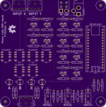
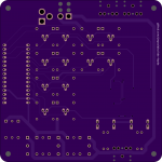
Out of curiosity, I wanted to see if it would be possible to source all of the parts from tayda, so here is a variant which meets that bill.
The design is a bit different, as tayda stocks only 1 latching relay, which has a single 3V coil. We can work with that by ganging pairs of coils in series to better work with our 9V supply. This requires a bit more sophisticated switching, using P-channel and N-channel FETs in an arrangement somewhat akin to an H-bridge.
Example of switching operation: To switch K1 and K2 in one direction, put 0V on PCH1 and 5V on NCH1. To switch them in the other direction, put 0V on PCH2 and 5V on NCH2.
Edit: hmm, actually I'm not 100% sure a 2N7000 will be saturated with 5 volts on the gate...
Attachments
Last edited:
I wanted to completely disconnect the headphones, for two reasons: 1) for paranoia / extra safety in cases where an amp uses no output capacitors and a virtual ground which is sitting at several volts, and 2) to absolutely eliminate any possibility the user can hear and count pops / clicks through their headphones as the input relays are switched several times.
In reality, probably not necessary in either case. In that case, just chalk it up to an OCD need for symmetry
Re: 2N7000: I pulled a 2N7000 out of the junk bin, put 5V on the gate, drove the drain with a constant current lab supply. Results: 100mA @ 0.34V = 3.4 Ohms, 200mA @ 0.72V = 3.6 Ohms, 300mA @ 1.27V = 4.2 Ohms. The relay coils are 65 Ohms rated at 3V, so they only need 46mA, so the drop across the 2N7000 will be less than 0.34V, which should be fine.
Edit: oh, actually the BS250 datasheet says RdsOn could be 10 (typ) or as high as 14 ohms, so that's actually more of a concern than the 2N7000. Still, the budget should be OK for voltage drops: 9V battery, assume it droops to 8V under load, assume 0.33V each across the two shottkys, assume 0.66V across the PCH and 0.33V across the NCH, that leaves 6.33V for the relays. And the relays will actually work as low as 2.25V, so the circuit should work even when drooping the 9V down into 6V territory.
Edit 2: I can probably ditch that 0.1uF on the Arduino nano, I'm sure that board has its own on-board caps.
Last edited:

digitalWrite() - Arduino Reference
"The exception is the Arduino Nano, Pro Mini, and Mini’s A6 and A7 pins, which can only be used as analog inputs."
ARGH NOOOOOOOOOOOOO!!!
"The exception is the Arduino Nano, Pro Mini, and Mini’s A6 and A7 pins, which can only be used as analog inputs."
ARGH NOOOOOOOOOOOOO!!!
pvs, how would you implement “reroll” using 74-series logic? Generating random numbers? Storing and retrieving values from eeprom? Seems like that would be a lot more difficult in 74-series, but maybe I’m just not as familiar with it!
Thanks for the encouraging words, folks. And just to make it clear, don’t order those boards: arduino nano pins A6and A7 are incapable of driving a relay, so it won’t work. I’ll salvage the boards by using a few bodge wires to use the RX0 and TX1 pins instead.
Thanks for the encouraging words, folks. And just to make it clear, don’t order those boards: arduino nano pins A6and A7 are incapable of driving a relay, so it won’t work. I’ll salvage the boards by using a few bodge wires to use the RX0 and TX1 pins instead.
- Status
- This old topic is closed. If you want to reopen this topic, contact a moderator using the "Report Post" button.
- Home
- Design & Build
- Equipment & Tools
- Yet another ABX box!