Suppose you have a device that is to operate in Class A at 30W and has a Rthjc of 0.8°C/W.
Suppose it is to sit on a heatsink of 55°C and the thermal resistance case to sink is 0.2°C/W.
And you want to curve trace this devise under working conditions.
Then, even if you do it in pulse mode, you need to first keep the junction at 85°C at all times.
You can say, "I'll use a heater block at 85°C and then measure in pulse mode."
Fine, but you are assuming the Rthjc and Rthcs are exactly 0.8°C/W and 0.2°C/W respectively for all DUT's.
But as all things manufactured in this world, there are tolerances.
And if you are out by a degree of two, your curve tracing data would not be accurate to a percent or less.
Especially when you have devices like 2SK3497, etc.
We therefore run in continuous mode and use 55°C heater block.
And we can predict heatsink temperature quite accurately.
Cheers,
Patrick
The above applies when using the curve tracer to match a large population of devices.
For example power MOSFETs in Class A amps.
If you are just using the curve tracer to obtain a typical curve, and not bothered about devices variations,
then what I just said is of course not applicable.
Patrick
For example power MOSFETs in Class A amps.
If you are just using the curve tracer to obtain a typical curve, and not bothered about devices variations,
then what I just said is of course not applicable.
Patrick
Since temperature matters a lot, how about using a TEC kit?
TEC kit with some MCU control can set a temp desired for measuring or at least constant temp (as constant as possible), simulatimg the working condition of transistors.
Although, I always think that LKZ's tracer is not suitable for power transistors, it should just be used to check the property of these kind of transistors, the measurement values are just for ref.
After long researching and compare, I think it's possible to make good measurement of power transistor not to mention matching of them under amateaur conditions. Uh...and when I finally gave up, I felt relaxed so does my pocket.
Suppose you have a device that is to operate in Class A at 30W and has a Rthjc of 0.8°C/W.
Suppose it is to sit on a heatsink of 55°C and the thermal resistance case to sink is 0.2°C/W.
And you want to curve trace this devise under working conditions.
Then, even if you do it in pulse mode, you need to first keep the junction at 85°C at all times.
You can say, "I'll use a heater block at 85°C and then measure in pulse mode."
Fine, but you are assuming the Rthjc and Rthcs are exactly 0.8°C/W and 0.2°C/W respectively for all DUT's.
But as all things manufactured in this world, there are tolerances.
And if you are out by a degree of two, your curve tracing data would not be accurate to a percent or less.
Especially when you have devices like 2SK3497, etc.
We therefore run in continuous mode and use 55°C heater block.
And we can predict heatsink temperature quite accurately.
Cheers,
Patrick
Patrick, this is of course the exact method to do it, as I have come to expect from you

And, in Class A amplifiers, especially if you want channel-channel distortion matching (or cancellation), thats the way to go. As DIYers, we want precision, and have time....
In the company I work for we do a lot of those, and I am afraid there might be some corners cut in the process. Essentially, we would measure a handful of devices where technology development tells us they represent the center of the parameter distribution, and then take the most meaningful to create a SPICE model. Usually they are quite ok, it all depends on the skills of the guy doing the model (which is true for most semiconductor companies....)
I actually contemplated at some point to select some devices, measure and create individual simulation models, then simulate the circuit and measure if the real thing actually behaves the same.... a lot of work to prove a point thats possibly proven multiple times.... what the heck, if I have some time in the future I might still do it
(have to build my F5X first
)
Last edited:
> It takes more time but is more precise if the device is parked at Vcc = Icc = 0,
> and only one data point is taken per second to keep the average dissipation low.
> Maybe it could work faster, depending on the time it takes to generate one data point.
That is only the case if you want to measure at Tj=22°C exactly.
In e.g. a Class A operation, the DUT sees a continuous DC dissipation.
That is not possible with this device.
Hence we make our own to operate at continuous mode.
Many power devices are extremely thermally sensitive.
So the only truth is to measure at operating conditions, which has a contnuous Iq.
Patrick
Efficiency of a class A amplifier in actual work is 0 to 0.5, so if it draws ~constant current at constant VCC, Tj is not constant.
It would already be a step forward if the low dissipation part of the trace
was not taken at Tj = 20°C and the high dissipation part at 150°C.
You have to teach me how to convert measured data to customised Spice files.
Does it prequire proprietary software ?
Cheers,
Patrick
That would probably do it. If you negotiate the price, you may get
a free Semiconductor analyzer.
Device Modeling and Characterization Products | Keysight
You have to teach me how to convert measured data to customised Spice files.
Does it prequire proprietary software ?
Cheers,
Patrick
Unfortunately I am no expert in this, although it was the subject of my studies and quite a bit of work in the industry. Generally speaking, the simulator model needs to be fitted to what the measured data shows, using approximation algorithms on a multi-dimensional problem and that can be time-consuming, and create imprecisions downstream in areas not expected.
However, there is no such thing as a "golden" device , representing the center of the parameter distribution. Plus, one measurement may not deliver all data needed (DC curve tracer versus noise meter versus thermal measurements versus high frequency measurements, mostly), so multiple data sources need to be combined.
Talking to the experts in our company, they all use custom software to convert a statistically significant number of measured devices into a data set for models, and it forces us to own licenses to multiple simulators (SPICE flavors, Simetrix, PLECS, .... you name it) to verify the performance, and thats a lot of work. No wonder the quality of the simulation models is all over the place, and that may have contributed to the so-so reputation of simulations.
In fact, I was looking at this curve tracer to see if it can easily create SPICE models, but that doesnt seem to be the case. And writing my own software to do that job would be another one of those projects
That would probably do it. If you negotiate the price, you may get
a free Semiconductor analyzer.
Device Modeling and Characterization Products | Keysight
Nice find, and impressive software capability! Unfortunately, not really accessible for us mere mortals....
Looks like PSPICE has that functionality:
SPICE modeling of a JFET from Datasheet - YouSpice
unfortunately, we just can't dump a measurement file into it and get a spice model in return, with just a few clicks
SPICE modeling of a JFET from Datasheet - YouSpice
unfortunately, we just can't dump a measurement file into it and get a spice model in return, with just a few clicks
Nice find, and impressive software capability! Unfortunately, not really accessible for us mere mortals....
I've seen it cracked in the wild, but it makes no sense. You need a paid full time job
to master that stuff.
I've seen it cracked in the wild, but it makes no sense. You need a paid full time job
to master that stuff.
Like with many tools that are supposed to make our life easier.....
On Windows 7, the curve tracing software app says something like "Device Not Connected" every single time. My workaround is to ignore that message and simply click Configure --> Get Parameters anyway. Presto, a popup notification message appears: "Parameters have get from device" and everything works smoothly thereafter.
The program uses the COM port number saved in the ini file directly when measuring.
When you change the USB port, windows will generate another COM number, which is different from the original one, so the program can't be connected, so you need to re-detect it in the settings to use the new COM port number. and many USB printers also produce the same phenomenon.
When you change the USB port, windows will generate another COM number, which is different from the original one, so the program can't be connected, so you need to re-detect it in the settings to use the new COM port number. and many USB printers also produce the same phenomenon.
The program uses the COM port number saved in the ini file directly when measuring.
When you change the USB port, windows will generate another COM number, which is different from the original one, so the program can't be connected, so you need to re-detect it in the settings to use the new COM port number. and many USB printers also produce the same phenomenon.
On Windows 7, the curve tracing software app says something like "Device Not Connected" every single time. My workaround is to ignore that message and simply click Configure --> Get Parameters anyway. Presto, a popup notification message appears: "Parameters have get from device" and everything works smoothly thereafter.
Bingo!
Thank you LZ!
Mark,
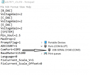
once you get parameters, save the setting in that screen. That will generate an INI file on your desktop (watch folder settings). The INI file must match the COM properties of the device in the device settings. After that, the deice shows up as detected every time.
In my case the PC picked up the device on COM3 and the original INI file was set to COM1. After I saved the config, the INI file changed to COM3 (below).
Attachments
Last edited:
- Home
- Design & Build
- Equipment & Tools
- Curve Tracer of LockyZ: Better UI and Translation