If you read the thread at the begining I wrote, people knows this is a 3rd-party modification, I don't think people will consider it to be official release, I made it very clear, and it takes many time to correct the "Chinese-English".
Also I don't benefit from it; I will withdrawl my work, if you think this would make you business better.
Also I don't benefit from it; I will withdrawl my work, if you think this would make you business better.
Hi,
@locky-z
could You please say something to the problem erikovsky detailed in #1 which I also reported in #3?
I waited now a couple of years and ordered the curve tracer as soon as it was offered again.
But at the time I´m really disappointed as it doesn´t seem to function correctly.
Also You never gave a rating on my ebay purchase, while you got instantly payed and got a good rating from me.
That´s certainly not the way to build confidence.
So I´m kindly asking You to offer a solution to the problem.
jauu
Calvin
I don't know what fault you're describing,Hi,
@locky-z
could You please say something to the problem erikovsky detailed in #1 which I also reported in #3?
jauu
Calvin
Hi,
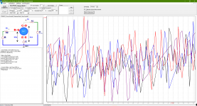
sometimes I get the same curves as shown in #1, but more often the curves begin as one would expect but break up like in #1 when the power levels increase.
I took care when setting the parameters to stay well within the DUTs limits.
My lab supply puts out 32V/3.2A at maximum (and I only tested with lower settings) ... staying within the limits of the curve tracer.
It looks as if the curve tracer for the most is producing wild cards.
jauu
Calvin
I don't know what type curve you're measuring.
The curve display is not smooth and is related to many situations, such as:
1.Y-axis scales are different, for example, the same curve under 0.5 and 5 on the Y-axis scale, and the fluctuations will be significantly different.
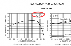
2."Hfe-Ic" curve, Y axis is Ic/Ib, at the beginning of the curve, Ic and Ib are particularly small, the measure result is not accurate. When perform a divide operation "Ic/Ib", the result amplitude changes particularly severely.
The curve display is not smooth and is related to many situations, such as:
1.Y-axis scales are different, for example, the same curve under 0.5 and 5 on the Y-axis scale, and the fluctuations will be significantly different.
2."Hfe-Ic" curve, Y axis is Ic/Ib, at the beginning of the curve, Ic and Ib are particularly small, the measure result is not accurate. When perform a divide operation "Ic/Ib", the result amplitude changes particularly severely.
This happened to meI've had one of his earlier models. I inadvertently had power applied on the psu, plugged in the connector, got a large spark, then nothing. I ended up replacing parts with new ones and took the easy route of sourcing a new relay with the same part number from China, but I think the quality of those relays are iffy because it acts up from time to time. Locky_z helped me through it but you would think a primo version would work out for him with less support issues.
Sent a message to Locky to se where to check first and what to replace
I did get it to work. It didn't like being plugged in to a USB hub and I started the powersupply at 2 volts and slowly ramped it up to 32 and it came alive
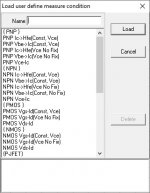
Since I've never used one before can somone suggest what template to load in the tracer to match BC556 (PNP) and BC546 (NPN) for Hfe and what settings to use. I'm kind of lost in that area and I've never used anything precise like this to match. The circuit runs at 20Vdc so I'm guessing I want to match for that voltage but other than that?
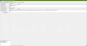
Here's the templates available and a screencshot of the settings for one of the PNP templates
Since I've never used one before can somone suggest what template to load in the tracer to match BC556 (PNP) and BC546 (NPN) for Hfe and what settings to use. I'm kind of lost in that area and I've never used anything precise like this to match. The circuit runs at 20Vdc so I'm guessing I want to match for that voltage but other than that?
Here's the templates available and a screencshot of the settings for one of the PNP templates
Attachments
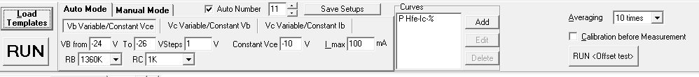
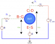
To measure hfe-Ic curve, also use 'Auto mode'->'Vb variable/Constant Vce'
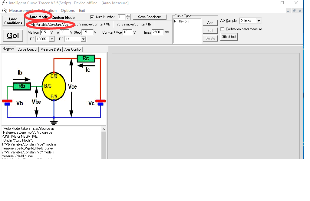
this mode have two control voltage:Vb and Vce.
(1)
'Vb' generates a base current through RB,
Because of the supply voltage limit, the absolute value of the maximum output is less than the supply voltage-4~-6V. If you use 32V power supply,the Vb maximum is 28V or -28V.
select another RB range will gererate different class base current. example use RB=1360K, and VB set "1 to 28V step 0.5V", then the Ib is about 0.7uA~20uA. If select RB=500ohm, Ib is about 2mA~28mA.
(2)Ic=Hfe*Ib
also supply voltage limit, the “Ic*Rc+Vce” must less than the supply voltage-4~-6V. If you Ic is about 30mA, and you select RC=1K, then the Vce can not reach to 10V, because the Ic*Rc=30V and your power supply just 32V.
note: Do not measure small currents with small RC resistors due to measurement accuracy limitations.
Example you Ic is about 1-10mA, and you select RC=5ohm. The measurement will be bad. because the Ic*RC=50mV, The curve tracer resolution is approximately 1-2mV.For better results, the pressure drop on the RC/RB resistor is greater than 0.5V.
(3)How much should I set Vce?
You can find the value on the ‘Hfe-Ic’ curve on the transistor pdf.

(4)If you measure PNP, you need set the voltage to negative.
this mode have two control voltage:Vb and Vce.
(1)
'Vb' generates a base current through RB,
Because of the supply voltage limit, the absolute value of the maximum output is less than the supply voltage-4~-6V. If you use 32V power supply,the Vb maximum is 28V or -28V.
select another RB range will gererate different class base current. example use RB=1360K, and VB set "1 to 28V step 0.5V", then the Ib is about 0.7uA~20uA. If select RB=500ohm, Ib is about 2mA~28mA.
(2)Ic=Hfe*Ib
also supply voltage limit, the “Ic*Rc+Vce” must less than the supply voltage-4~-6V. If you Ic is about 30mA, and you select RC=1K, then the Vce can not reach to 10V, because the Ic*Rc=30V and your power supply just 32V.
note: Do not measure small currents with small RC resistors due to measurement accuracy limitations.
Example you Ic is about 1-10mA, and you select RC=5ohm. The measurement will be bad. because the Ic*RC=50mV, The curve tracer resolution is approximately 1-2mV.For better results, the pressure drop on the RC/RB resistor is greater than 0.5V.
(3)How much should I set Vce?
You can find the value on the ‘Hfe-Ic’ curve on the transistor pdf.
(4)If you measure PNP, you need set the voltage to negative.
Attachments
Some further mod based on erik's work.
Please unzip and overwrite the ads7871_V3.exe
As for manaul, it's painful to translate, so anything that is unclear and unrealizable from the UI or manaul, please feel free to let me know, I can make better translation. This is important for upcoming users, especially newbie for measuring transistors.")
All newer version will be downloadable at GitHub:
Releases * Erikovsky/Tracer-System * GitHub
Please unzip and overwrite the ads7871_V3.exe
As for manaul, it's painful to translate, so anything that is unclear and unrealizable from the UI or manaul, please feel free to let me know, I can make better translation. This is important for upcoming users, especially newbie for measuring transistors.
All newer version will be downloadable at GitHub:
Releases * Erikovsky/Tracer-System * GitHub
Attachments
Last edited:
Any other suggestion about the software? I am doing further change, so please feel free to give me feedbacks.
Any problem on reading technical manuals? English version is under work.
Yes. It seems, the entire sweep is done as one piece. That leads to a changing DUT
temperature during the measurement, and as a prof. of mine used to say:
The only thing constant with a transistor is its weight.
It takes more time but is more precise if the device is parked at Vcc = Icc = 0,
and only one data point is taken per second to keep the average dissipation low.
Maybe it could work faster, depending on the time it takes to generate one data point.
Probably only Locky-Z can do that.
Gerhard
> It takes more time but is more precise if the device is parked at Vcc = Icc = 0,
> and only one data point is taken per second to keep the average dissipation low.
> Maybe it could work faster, depending on the time it takes to generate one data point.
That is only the case if you want to measure at Tj=22°C exactly.
In e.g. a Class A operation, the DUT sees a continuous DC dissipation.
That is not possible with this device.
Hence we make our own to operate at continuous mode.
Many power devices are extremely thermally sensitive.
So the only truth is to measure at operating conditions, which has a contnuous Iq.
Patrick
Most power devices will settle within 100us (a.k.a. 10kHz square wave), and thats how (big) power semis are measured - very short pulses. Most of them have a "thermal impedance" diagram in their datasheets, showing how long your pulse can be (voltage / current) until you reach maximum junction temperature. It also tells you how much time is needed to cool down between pulses.
- Home
- Design & Build
- Equipment & Tools
- Curve Tracer of LockyZ: Better UI and Translation