I'd like to put together a bench power supply for my ... "experiments". I don't really need regulation. I've got a little pile of filament transformers for 2.5V, 6.3V, and 12.6V. Planning to put all of them in a chassis with banana sockets. All the transformers for each voltage are identical, so I'm just going to parallel them. Each voltage will have its own fuse and power switch. Maybe a switchable doubler to get 5V from the 2.5V units.
For B+, I'm considering picking up a Hammond AO-32 power supply. Pretty cheap on eBay. It's got a massive PT with a 415/0/415 winding, a 2.5H choke, and a filter cap can. If I use diodes instead of tubes and bypass the choke, looks like about 525V with 150mA load. I'd run it through a variac to achieve lower voltages - manual regulation. About $40 for a used 120V/2A panel-mount. Maybe also have a switch to swap the choke for additional filter caps.
Does this sound reasonable?
It's not a good idea to parallel the secondaries of separate transformers.
They won't be identical, and will cross-feed. Series is ok, if you derate the string
max current to that of the lowest current winding.
Paralleling the identical secondaries of a single transformer is ok, if you observe phasing.
Watch the voltage rating of the capacitors in the Hammond supply, they may not be adequately
rated for 525VDC use. Without the choke there will be a lot more of the 120Hz sawtooth left,
especially at higher current loads.
Last edited:
It's not a good idea to parallel the secondaries of separate transformers.
They won't be identical, and will cross-feed. Series is ok, if you derate the string
max current to that of the lowest current winding.
Paralleling the identical secondaries of a single transformer is ok, if you observe phasing.
Interesting - I thought that with units from the same mfr (Triad), with the same date code, they would be close enough. But that's fine, I can easily just run each one to its own jack on the panel. Not likely to need more than 1.3A on any one 6.3V tube.
Watch the voltage rating of the capacitors in the Hammond supply, they may not be adequately
rated for 525VDC use. Without the choke there will be a lot more of the 120Hz sawtooth left,
especially at higher current loads.
Oh, definitely. The caps are from the 1950s, so I'd replace them anyway with doubled-up 400V-rated caps.
Thanks for the input!
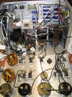
This is what happens when you let a simple DIY bench supply go a bit wild.
18 x 8 x 14 inches. 2 chokes, 2 variacs, 9 transformers, 10 fusees, 60 pounds.
Goals, man. Seriously. Very nice.
")

I'd add an RC (10k and 22uF) between the tripler and the pot. As-is, the ripple gets worse and worse
as you turn the pot towards maximum negative voltage.
Like this? With the filter cap before the pot, ripple is down to about 0.02V at -70V, and 0.002V at -7V. I'll totally take that.


Here's what I did. I know you weren't planning to do something regulated, but here's one option if you have second thoughts. If you want to skip past my learning about MOSFET safe operating area (and why MOSFET datasheets are often wrong), skip to page 3.
High Voltage Bench Power Supply Design - Page 1
I've used this power supply a lot and done some very unkind things to it. It works pretty well and has been very reliable. I was cheap and used a control transformer for the main power transformer. I've seen them go for $20, or you can dumpster dive it.
Welp, I came across another transformer in the pile, much better suited - nominal 24V, yielding 80Vpp.....
That sketch with a 24V AC winding thru FWB will make 36V DC, not 75V. You may want a Doubler.
Many grid specs want low resistance bias, 50k max for some tubes. I'd want the bias pot more like 10k or 25k than 250k.
That sketch with a 24V AC winding thru FWB will make 36V DC, not 75V. You may want a Doubler.
Good catch. I'm still learning my way around LTspice, so I thought that the "amplitude" parameter was peak-peak, rather than just peak.
Many grid specs want low resistance bias, 50k max for some tubes. I'd want the bias pot more like 10k or 25k than 250k.
Done and done. Had to lower the 10k resistor, because the additional current draw was pulling the voltage way too far down. Ripple with this circuit is about 0.01V. And one fewer component!

Last edited:
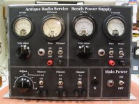
Aaaaand I just scored a Gelman 500V@150mA unregulated supply for $15 on eBay. With local pickup, so it's really that cheap! It's set up exactly like I was planning, with a big transformer fed by a panel-mount variac. The filtering is terrible (a single 20uF cap), but that's easily and cheaply remedied. The nominal 500V is actually 530 because my house sits at a healthy 122. I could even rewire the variac to add 10% and get up to 580 if I uprate the caps to 800V (which I'm doing).
While I wait for my new caps to come in, I've been reforming that lone electrolytic this morning, and got it stabilized at 500V in about two hours. Voltmeter is dead on. Going to test the ammeter this afternoon.
Best of all, there's a ton of empty space in the chassis and on the faceplate, so I can put the filament supplies in the same box - maybe even the bias supply!
Caution- having a big cap with high voltage connected to exposed terminals can be a real hazard. I would suggest a relay to discharge the cap when the power is removed. 20 uF at 400V is a lot of energy already. Adding more could both be a serious hazard and stress the power supply excessively on turnon. And just because you discharged the cap removing a load can lead the the cap "recharging" itself to a hazardous voltage.
- Status
- This old topic is closed. If you want to reopen this topic, contact a moderator using the "Report Post" button.
- Home
- Design & Build
- Equipment & Tools
- Poor man's bench PS